Safe limit of twist in a shaft

For example, Let's imagine your PTO is a cylinder 1000mm long and 50mm (2") in diameter. It rotates at 300 rpm and has an applied load of 1000Nm. Using the material properties of 12L14 steel, there is a handy online calculator which shows an angle of twist of 1.2 degrees and a shear stress of ~41MPa.

The Yield Strength of the 12L14 steel is 415MPA, so you are at about 10% of the maximum torque you can place on that shaft before it begins to permanently deform.

At 300 rpm, this is about 31kW (42HP) through the shaft.


I used a modulus of rigidity of 77GPa as calculated from the elastic modulus and poissons ratio.

 
Why?

Been around ag for years (exposed to as they were my radio clients in past life) and down time expensive so just build it correct and be done.

If you have 100 hp in available power to the PTO then insure the shaft Jan handle more.

Place shear pin rated for attachment (usually in attachment) someplace.

If you want to measure for fun fine, there are devices for this that are not cheap.

You could build something that looks at difference of position of both ends of the shaft with simple electronics but the mounting of the sensors would be a challenge.

Many other things to play with that could be more interesting.

Sent from my SAMSUNG-SM-G930A using Tapatalk
 
your plan of using an optical encoder to measure the twist of the shaft and thus the torque may not be accurate enough. Also optical encoders do not work well in harsh/dirty environments. You can improve the resolution by enlarging the optical disk but that will make it unwieldly pretty fast. Also need to be sure you have a fast enough processor to accurately measure the timing differences of the optical input differences between the ends of the shaft at max expected RPM.
Interesting project
I was thinking of maybe those magnetic non contact shaft encoders. You can get high resolution but they are a bit pricy.


Each magnetic ring for a 2" PTO shaft is ~$300. This is one high end example and there might be much cheaper options. These come in 20 bit (1 million + counts per rev) resolution.

This could resolve (using my previous example) down to 0.2Nm of torque on a rotating shaft.
 
@mcardoso thank you for all that info. I am going to apply myself to everything you've said this evening and see if I can come up with numbers that I am confident in.


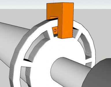
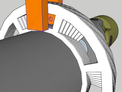
My plan (as described in post #1, everything up in the air right now) does not require high resolution encoders. I did not explain it fully in post #8; it was abbreviated for simplicity. I made it sound as if there will be two optical sensors; one at each end. Actually there will only be one. Instead of having a slotted disk at either end, one will be mounted at "end A", and the other will be mounted directly beside it. "End B" will have a tube fixed to it, running the length of the shaft back to "end A" and connect to the slotted disk. The optical sensor will be reading through both disks at once. The output of the optical sensor will basically be a PWM signal where duty cycle corresponds to torque and period corresponds to speed. Two variables in one signal. It will use use simple slotted disks, maybe 6 slots each, or however many it takes so they don't overlap at maximum twist. I think 6 pulses per revolution is more than enough; the only reason I am planning any more than one pulse per rev, is because I know that the speed (and?) torque in the shaft will be oscillatory any time there is any bend at the cardan joints and i want an average of the data for several sectors of the rotation. I do not believe I need high resolution encoders because I will be precisely measuring time. A crystal will be running and my microcontroller will be adding up the counts while the photointerrupter is off, and while it's on. Even a lowly 512kHz crystal would give me about 10,000 data points per slot, with 6 slots and running 540rpm.

If the above description is not clear, here is an early version picture of it. When I drew this up I was trying to maximize the difference in on-time vs off-time, so I had several disks which represent about a 15% duty cycle @ 0 torque, and they would fan out like a camera iris until fully closed. I later realized that this is pretty much pointless, with the accuracy of the crystal, I can just use 2 disks which each represent a 50% duty cycle. I am not going to use the stack of disks and the multiple nested tubes. Just the first disk, the last disk, and the outer tube.

Capture2.JPG
Capture11.JPG
Capture12.JPG


50% (50.0000%) duty cycle will be equal to 0 (0.00) ft×lbs. 0% will be equal to max. Anything in between will be whatever it is (empirically discovered). I can work out the real-world twist degrees per ft×lbs on the bench and scribe graduations on the disks, then verify the values my microcontroller spits out against a timing light.

P.s. I don't know why my last paragraph is in italics and I can't change it.
 
Why?

Many other things to play with that could be more interesting.

Sent from my SAMSUNG-SM-G930A using Tapatalk
Because.

I have unconventional interests. The torque sensing shaft project is an interesting enough project for me to pursue in and of itself. But, it is a means to an end. My tractor is the lowest HP variant (40HP) of a line of tractors that goes up to 55HP. They are all mechanically identical. Same heads, same pistons, same stroke, same fuel pump, same turbo. The only difference is varying levels of handicap in the ECU. I'm going to hack it and I need a way to quantify my results. Planning to use the PTO generator I'm building as a variable load to put behind this.
 
Last edited:
@mcardoso thank you for all that info. I am going to apply myself to everything you've said this evening and see if I can come up with numbers that I am confident in.


My plan (as described in post #1, everything up in the air right now) does not require high resolution encoders. I did not explain it fully in post #8; it was abbreviated for simplicity. I made it sound as if there will be two optical sensors; one at each end. Actually there will only be one. Instead of having a slotted disk at either end, one will be mounted at "end A", and the other will be mounted directly beside it. "End B" will have a tube fixed to it, running the length of the shaft back to "end A" and connect to the slotted disk. The optical sensor will be reading through both disks at once. The output of the optical sensor will basically be a PWM signal where duty cycle corresponds to torque and period corresponds to speed. Two variables in one signal. It will use use simple slotted disks, maybe 6 slots each, or however many it takes so they don't overlap at maximum twist. I think 6 pulses per revolution is more than enough; the only reason I am planning any more than one pulse per rev, is because I know that the speed (and?) torque in the shaft will be oscillatory any time there is any bend at the cardan joints and i want an average of the data for several sectors of the rotation. I do not believe I need high resolution encoders because I will be precisely measuring time. A crystal will be running and my microcontroller will be adding up the counts while the photointerrupter is off, and while it's on. Even a lowly 512kHz crystal would give me about 10,000 data points per slot, with 6 slots and running 540rpm.

If the above description is not clear, here is an early version picture of it. When I drew this up I was trying to maximize the difference in on-time vs off-time, so I had several disks which represent about a 15% duty cycle @ 0 torque, and they would fan out like a camera iris until fully closed. I later realized that this is pretty much pointless, with the accuracy of the crystal, I can just use 2 disks which each represent a 50% duty cycle. I am not going to use the stack of disks and the multiple nested tubes. Just the first disk, the last disk, and the outer tube.

View attachment 360397
View attachment 360398
View attachment 360400


50% (50.0000%) duty cycle will be equal to 0 (0.00) ft×lbs. 0% will be equal to max. Anything in between will be whatever it is (empirically discovered). I can work out the real-world twist degrees per ft×lbs on the bench and scribe graduations on the disks, then verify the values my microcontroller spits out against a timing light.

P.s. I don't know why my last paragraph is in italics and I can't change it.
OK I think I am following...

So the solutions I have written about above are extremely close to the manner of measurement in video #1 in post #1. You'd need to track the positions of two encoders (zeroed out under zero load), query them for their current position simultaneously, compare the readings to determine twist, then use math to calculate torque from twist. You could also sample the tractor side encoder for the speed, multiply that by the torque, and get shaft power. The resolution of torque would be directly related to the resolution of the encoder, the geometry of the shaft (how much it twists for a given torque), and the distance between the encoders (as large as possible). If the distance between the encoders can be increased, then lower resolution (cheaper) encoders can be used.

I am following your plan as well, but would like to offer some dissenting opinions about the method based on my personal hands on experience. First off, feel free to ignore me and try it anyways. Second, prove me wrong, because I'd love to learn new methods like you are discussing.

I believe you are planning to use a "transmissive photomicrosensor" as they are they are commonly called. These output an analog voltage (or sometimes a PWM duty cycle) which corresponds to the amount the sensor is blocked. These work, although they have a few notable drawbacks.

First off, the sensing window is small, forcing you to limit the measuring distance to a very short range (0.25" as an example). In your application, you will want to maximize the distance between the discs as to have a more noticeable twist in the shaft (which even over a good distance like 3 feet might only be a few degrees). The short distance would greatly limit the signal to noise ratio, perhaps to the point where there is no measurable twist between the discs.

Second, the sensor is an optical sensor which is very sensitive to ambient light and will report false signals from even a small amount of stray light - this will drastically reduce your signal to noise ratio. It will also be very sensitive to contamination from dirt, dust, or water.

Finally, the voltage output from these sensors will is nonlinear and will require some mapping tables in code to calibrate the voltages to the actual twist in the shaft. You'll probably end up needing to calibrate the whole thing manually and will end up with a very poor signal to noise ratio.

If you want to go this route, you might want to consider two sensors each with a single disc (just like you have pictured above) positioned as far apart on the shaft as possible. Instead of measuring the exact angular displacement as in my encoder example above, you would be comparing the timing of the light to dark transitions on each of the sensors. In this case an active photosensor with built in amplifier and comparator woud add a lot of robustness to the design. Link below.


By knowing the exact speed of the shaft (read one of the discs like an encoder for speed), you can calculate the angular distance traveled by the shaft during the delay between the light to dark transition on each of the discs. It would be very difficult to align the discs mechanically so each had a light to dark transition at exactly the same time under no load, so it would require a calibration cycle with the shaft running under no-load to determine a nominal delay time between each disc. Once that is defined you can load the shaft and the difference between the measured delay and nominal delay would give you the twist in the shaft. Again once you know this, a bit of math will give you torque and power. The sampling rate of the microcontroller to the sensor input would be the limiting factor in the resolution of torque. You would also need a very accurate measurement of shaft speed, so a disc with a higher pole count would be beneficial to a point although a dozen or so poles would be sufficient rather than the million pulses of the encoder idea.

The downsides are that this could not measure the torque on a non-rotating shaft where the encoder method could, and you rely on a very fast microprocessor to sample the signal for good resolution where that is not a requirement for the encoders. Also it is still an optical system so contamination is a real risk. The sensors I linked are at least waterproof.
 
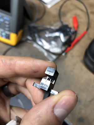
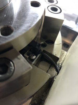
I am working on an industrial robot which used those transmissive photomicrosensors. They were a total pain and very finicky. It took me a long time to find those amplified output sensors with built in comparators but they worked great for my application.

Here is a photo of the original sensor

Image081.JPG

And the new active amplified sensor installed in the robot joint.

Image143.JPG
 
I wanted to work out a math problem for the last idea I presented.

Let's assume the sensors are on a 2" solid round 41L40 steel shaft located 36" apart. Each disc has 8 dark to light transitions (8 slots) and we plan on triggering on the rising edge of the sensor (the dark to light transition).

During the calibration run (no load) we read the sensor located on the tractor end of the shaft and detect a rising edge transition every 25.000ms. 0.025 seconds * 8 slits per revolution = 0.2 seconds per revolution. This is 5 revolutions per second or 300.00 RPM.

OK cool. Now let's assume during the no load calibration run we determine the time delay between the dark to light transitions on one disc to the same transition on the other disc is 1.000ms. We save this in the back of our minds. This is due to the inaccuracy in disc mounting.

Now we restart the test but with an applied load. We again measure the shaft speed and find it to be 300 rpm. We also find the delay between the mounted discs to be 1.200ms. We must subtract the calibration value of 1.000ms from this to find the time difference under load of 0.200ms (200us).

We know the shaft is rotating at 5 revolutions per second, so we calculate that 5 rev/s * 0.000200 s = 0.001 rev or 0.36 degrees.

Again using that online calculator we can calculate the torque given a shaft radius of 1", a length of 36", a twist of 0.36 degrees, and the mechanical material properties of 41L40 steel. This returns a torque of 358 Nm and a shaft power of 15.1HP.

All this information is given by measuring the relative timing of two sensors on the shaft.

It is not critical that the shaft be rotating at exactly the calibration value as the calibration delay can be converted to an angular misalignment measurement which can be applied to measurements at any speed. It is critical that the exact shaft speed be measured right as you are measuring the time delay between the sensors for best accuracy (both during the calibration run and the test).
 
Last edited:
An interesting thought experiment.
 
Back
Top