Safe limit of twist in a shaft

Have you read some pages describing the relationships? Like: https://www.engineeringtoolbox.com/amp/torsion-shafts-d_947.html

Do that and ask if you have any questions. I’d think you can approximate with a solid or hollow shaft section, over which you will measure twist. You definitely don’t want to exceed the yield strength, and ultimately you’d want to build in a safety factor. But you should be able to get a first-order analysis going pretty easily.
 
Why go with extreme twist? Typical strain gauges can measure pretty small deformation. You'd just need to calibrate the shaft under a known load. This also saves doing complex analysis on the shape and type of material. This is done all the time without getting anywhere near any limits of the material strength.

The only minor issue I see is that PTO shafts need to telescope dynamically to account for lifting/lowering the implement, and possibly for following ground contour such is in a large mower deck.

www.sparkfun.com has some basic electronics for working with strain gauges and load cells.
There isn't a whole lot of opportunity to put a strain gauge into the mix. That was my original idea (measuring side thrust on my belt reduction) and I couldn't convince myself that it would work, and also I want this to work on multiple implements. If I made a strain gauge part of of the shaft then I would either need to put a 4-wire slipring on it or put the amplifier on the shaft as well and wirelessly transmit the info.... actually, that's kinda feasible. Should run off a battery just fine, at least for proof of concept. Maybe final rev could have some coils that rotate past fixed magnets; a tiny little generator to power the electronics
 
I was talking about permanent deformation. I've run hay balers, hay cutters, peanut diggers and combines, post hole augers, feed grinders, etc. I'm sure there is a bit of deflection in a PTO driveshaft, but I would think it would be less than ten degrees or else it would either be twisted or broken at the end of a job. I'm going out on a limb with a wild guess, but I'm thinking somewhere along the lines of five degrees or less. This is just based on experience and the Mark One Eyeball.

Mike, loved the comment on the 'holy shear pin'!
 
<snip Now, you say it's as simple as shear stress. I want to believe that, and I promise to spend the next day or two trying to convince myself of it, but I have a lot of mental hurdles to overcome before I get "there."

To be clear, I was referring to the shear stress (T max) as defined in the linked calculations. Not a single or double shear value from a table in Machinery Handbook.
 
The key number you need to watch is the stress. You need to be well under the endurance limit for your tube material. This is the stress below which you stop seeing fatigue failures.

Also, the important part about the twist is not the total twist but the twist per length. If your shaft is a mile long, then a full revolution is a minuscule stress or strain. If it's an inch long, you probably twisted it off ;-)

You can do RF transmission of strain gauge data for torque measurement, bit it's a fiddly little signal. I've done it on tractor trailer drivelines in frac service.

Sent from my SM-G892A using Tapatalk
 
You can do RF transmission of strain gauge data for torque measurement, bit it's a fiddly little signal. I've done it on tractor trailer drivelines in frac service.

Sent from my SM-G892A using Tapatalk
Can you share any specifics about how you implemented that?

Thinking more about the strain gauge idea, this gives the opportunity to put the measurement device on the tractor, which is preferable as the torque (? Or at least the speed?) In the shaft will oscillate any time it isn't going straight out to the load (which is always). It could be some kind of thing that fits over the spline shaft and has another spline shaft sticking out of it.
 
If you're doing this on a real-world farm implement you have some significant environmental challenges that will need to be addressed. Water, mud, crop/weed debris, high/low temperature, vibration, errant lube or hydraulic oil contamination etc. I don't have a specific solution for you, just a lot of things to watch out for. Example: strain gauges typically are glued on to the thing they're monitoring. Many adhesives don't like wide temperature swings or long term exposure to water or high humidity.

I also am wondering about the compatibility of a strain sensor & wireless sender with the safety shield that typically is around the PTO drive shaft. If you remove yours for this, you're living dangerously.

A couple of magnetic sensors looking at magnets attached to each end of the shaft to look for phase shift differences between them as the shaft twists under load _might_ be robust enough (and might work with the drive shaft safety shield), but that's just armchair engineering. There's lots of magnetic junk out there that could clog up the works, so to speak, so that approach may not be bulletproof, either. If nothing else, naturally-occurring magnetite in the soil will eventually cause magnets to grow a nice beard of magnetic particles.

Shear pins. They work on my tractor. I've gone through quite a few. And thanks to them, I still have a working mowing deck and tiller.
 
Wow! Bunch of replies here.

If you have a cylindrical or tubular section in the middle without a keyway then the math is pretty simple. I have a textbook I can pull out and try to work through some of the math with you.

The core principle for all materials is the stress-strain curve (see image below). Stress is the force per unit area in the material and strain is the deflection per unit length.
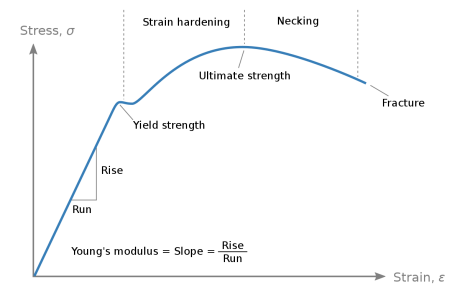
1616505857624.png

As the applied force (torque in your case) increases, the stress in the material rises. For simple shapes, the calculation of stress is easy, but adding a keyway to a shaft significantly increases the stress concentration at the corners of the keyway. Anyways, as stress goes up the material immediately deforms and starts to stretch or twist. As long as the stress stays below the yield strength the material will return to the original shape when the applied load is removed (just like a spring). If the applied stress goes above the yield strength of the material, a permanent deformation will occur. The material must still spring back the equivalent amount of strain before the yield strength; you notice this when working on sheet metal and you must deal with spring back.

Anyways as more and more load is applied, the stress in the material strain hardens until it reaches the Ultimate Strength. At this point, if the applied load remains, the material rapidly fails until fracture occurs.

In brittle materials (glass, ceramics, etc.) the fracture strength is lower than the yield strength and they will crack before plastically deforming.

Here is a great link that shows the formulas for calculating stress in common shaft shapes.


If you stay below the Yield strength, the shaft will deform elastically (not permanent), and the deformation will be linear to the applied force, making a great torque meter using two encoders as you showed above. The relationship for stress/strain below the yield strength is Youngs modulus, a published value for most materials.

One other value you need to be aware of is the fatigue strength. This is a value of stress (typically below the yield strength) where repeated cycling of the load will tend to generate and grow cracks. Cracks have a very sharp tip which will concentrate the applied stress at a stress concentration (or stress riser). This causes local deformation and crack propagation. You typically want to design below this limit in designs that have cycling loads applied to them.


What I find very interesting is that steel, titanium, and some other metals have a defined endurance limit where they will weaken from repeated load cycles, but only to a point, from there they retain their remaining strength for infinite cycles of the same applied stress.

Other metals like copper and aluminum have no endurance limit and will eventually fail under even the smallest cycling loads (after a crazy number of cycles).
 
Last edited:
So I guess what I want to say is this. If you have a simple shape (round, tube, or hex) then you can calculate the stress from applied load or vice versa. You can calculate the stress from the strain (using Young's modulus), and you can measure strain using two encoders a known distance apart.

As long as you keep the applied load safely below the Yield Strength of the material, then with a bit of math, you can calculate torque from the difference in readings between the encoders.

You'll need very high resolution encoders as the amount of twist in the shaft under load will not be much.
 
Back
Top