PM Research #7 It Begins

That's either a large cylinder or a small lathe/chuck.
My 10" 4 jaw makes the little cylinder look even smaller.

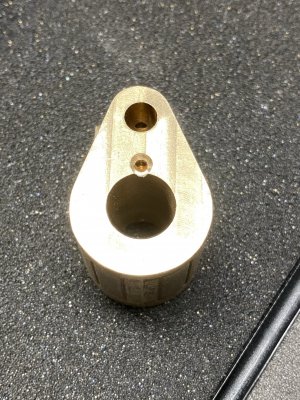
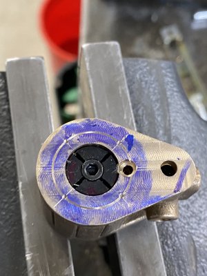
The #6 cylinder is quite a bit bigger than the #7. The bore is 1.5".

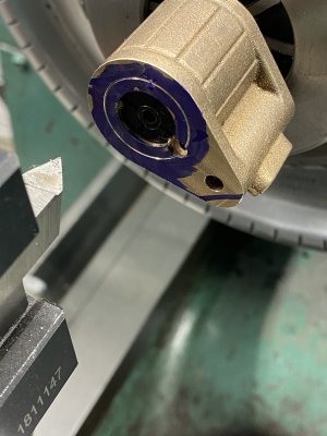
That is an 8" 4 jaw chuck and it was darn close to running out of thread on the one jaw sticking out. Ran it VERY slowly for this operation.
 
That is much bigger than my .500" bore.
If I get through this build which will take quite some time, I am leaning more toward larger components. This little stuff is tricky but I'm learning a ton.
 
That is much bigger than my .500" bore.
If I get through this build which will take quite some time, I am leaning more toward larger components. This little stuff is tricky but I'm learning a ton.

It is all a blast. I've set the #6 aside to work on another project, but I am about 70% done with it and have about 80 hours into the machining. I screw up at least once per part which is annoying.
 
learning to find center and how to accurately measure where features go is the learning curve. I was watching Kieth Appleton, he is able to eyeball many of the tasks.
I use my DRO and edge finder as much as possible. The coaxial center finder is a great tool as well, wiglers etc.
 
When I started reading some of the model engine builds I thought " I would like to try that " then I realized my skills are not there yet lol Your doing a wonderful job , Al

Build your skills by doing! I learned a lot with my first engine. It's not the best but it runs.

Eric
 
Made some time for the left cylinder yesterday. Once again working with this odd shaped little fellow was challenging but the 20 degree 3/32” holes went off without a hitch, whew. Once you get this far it would be awful to screw it up.
 

Attachments

  • 41D2AE08-0A4A-4A1B-B6C1-88606452ED0F.jpeg
    41D2AE08-0A4A-4A1B-B6C1-88606452ED0F.jpeg
    796.4 KB · Views: 16
  • A3883B90-0C61-4D4F-8648-31D9F5F87EC0.jpeg
    A3883B90-0C61-4D4F-8648-31D9F5F87EC0.jpeg
    951.9 KB · Views: 18
  • 4FB75389-1105-427E-8D87-E40A5D6B6A6B.jpeg
    4FB75389-1105-427E-8D87-E40A5D6B6A6B.jpeg
    809 KB · Views: 23
I’m very happy with the concentricity of the lay out and the drilled and tapped 5-40 holes.
This is pucker time.
I watched a Mr. Pete video where he used the lathe to make a ring at the bolt circle. I moved out .375" from spindle center using a micrometer on a magnet to verify the dial movement.
I need some 5-40 transfer screws for the caps.
 

Attachments

  • DC5F31C3-4289-496C-A70C-602203C3B6E4.jpeg
    DC5F31C3-4289-496C-A70C-602203C3B6E4.jpeg
    812.4 KB · Views: 23
  • D5DED3E1-C85C-46D2-B539-FE5BAEBD5506.jpeg
    D5DED3E1-C85C-46D2-B539-FE5BAEBD5506.jpeg
    1.3 MB · Views: 20
  • E87ED666-B7BA-4EEC-8FCF-090D79CE8DAE.jpeg
    E87ED666-B7BA-4EEC-8FCF-090D79CE8DAE.jpeg
    1.3 MB · Views: 19
  • D0E11A24-8FE5-48AD-86D5-6733EAC41F05.jpeg
    D0E11A24-8FE5-48AD-86D5-6733EAC41F05.jpeg
    1.4 MB · Views: 20
  • CD7980D7-008A-4D9A-8F02-B6516EA84CC5.jpeg
    CD7980D7-008A-4D9A-8F02-B6516EA84CC5.jpeg
    1.3 MB · Views: 27
Last edited:
I need some 5-40 transfer screws for the caps.
Now, the only reason I say I need transfer screws is I went about this wrong. After watching Joe Pi do this with the DRO, independently mind you. he says, trust but verify, hmm, that sounds familiar.
I should have drilled the heads first then transferred with the transfer punch!!
Ah, we'll get there in the end. Those transfer screws are almost too small for my fat fingers.
This is why it amazes me that people use the lathe for the bore on these engines instead of the mill. I found it SO much easier to do a facing op on the mill, then boring head for the bore, drill/ream the valve, use the DRO for the bolt circle.

Then flipped it over, indicated on the bore, then faced and DRO'ed the other bolt circle.

I didn't need to use transfer punches or transfer screws at all.
I think you just talked me into using the mill for the cylinder on the beam engine I'm building.
 
Back
Top