PM 1236 Sheave Mod

Ray C

Registered
Registered
Joined
Nov 16, 2012
Messages
5,596
Tomorrow I'll finish up all the work on the 1236 and at the last minute, decided to switch the V-belt sheave over to a flat belt. I had a blank piece of cast iron from a flat belt sheave I made a couple years ago that was never picked-up by the customer so, this whole job is being done with "drops" that are laying around. I decided to increase the diameters of the sheave to the extent they'll still fit. The ratios will be preserved of course. It will be a two-piece ordeal because the existing center hole is way too big so I'll make the hub out of aluminum because that's what happens to be laying around.

I haven't looked too closely yet but, there's probably room in the gear area to squeeze in an idler for the flat belt. We'll see...

Here's the old blank sheave, a hunk of aluminum and the two-step sheave from the lathe.
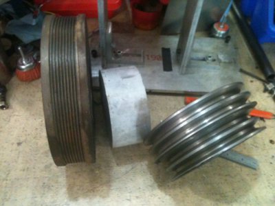
Sheave and Blank.JPG

I'm using a 5 groove flat belt and if they're good enough to run a power steering pump and an AC unit which easily sucks up 4-5 HP, it should be good enough for a 2 HP lathe. I left room on the sheave for a 6'th groove if it needs it. Time will tell.

About 3.5 hours later, it's ready for balancing... Oh, please pardon the hex bolts. I didn't have any 5/16" cap screws short enough. I'll get some tomorrow when I pick-up the belt which I calculate should be 34 or 34.5" which is commonly available.
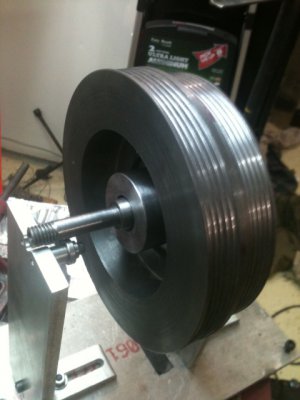
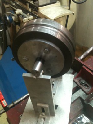
Side1.jpgSide2.jpg

Ray

Sheave and Blank.JPG Side1.jpg Side2.jpg
 
Minor hang-up... The motor has a weird keyway -very wide, a broach size I do not have on hand... Arghhh! Going to pull the motor off and cut a "normal" sized slot for for a 15/16" shaft. Probably can't get to it till tomorrow. Everything else fits nicely though.

Ray
 
Did you have a reason to go to a flat belt? I missed that.
 
Really disliked switching two V-belts to change speed sets. Flats are easier to slide over.

In process of setting-up the new bench, I discovered the main two-step sheave was out of balance so I took it off and started to static balance it and once it was off, I just thought... -well, might as well give the flat-belts a shot -now's a good as time as any.

If the flat belts don't pan out, it's no great loss. 10 bucks for the belt and the materials were just odds n ends laying around.


BTW: I figured-out a good way of putting a tensioner/idler in there which would work for either flat for v-belts... I'll toss that in there while I'm at it. -And drag this out even longer.

... I'm getting really grumpy with my shop all torn up. Had to take some shelves down to get the gantry in place and I got stuff scatter all over the place. -Driving me ape already.


Did you have a reason to go to a flat belt? I missed that.
 
I have been thinking about a belt tensioning system that would allow two belts on the motor pulleys to be installed and being able to change speeds by simply engage either belt instead of having to switch the belt from pulley to pulley.
Pierre
 
Not sure I follow you Pierre but sure sounds interesting. I wouldn't care if I had to deal with two belts of different diameters provided there were a "quick release" of some sort to release tension and allow a quick swap-over. The more I think about this, I may just install such a thing for the V-belts.

I'm sure you're well aware that belts flapping under tension and considerable speed accounts for a big chunk of vibration in a system. I went through all this with a 20kW diesel generator I built (from the ground up). There's a reason people like direct drive... Hmmmm, light bulb flickering in my head. Are you thinking what I'm thinking?


I have been thinking about a belt tensioning system that would allow two belts on the motor pulleys to be installed and being able to change speeds by simply engage either belt instead of having to switch the belt from pulley to pulley.
Pierre
 
Pierre,

FYI... I just measured the main sheave RPMs (with a LED tach). The motor in mine is a 3Ph and it spins 1780 @ 60Hz. The stock motors are a little bit slower; 1740 if memory serves. Anyhow at high ratio, the main sheave spins 1007 and at low ratio, 660. Just throwing that out there for the books. Also, after taking a closer look, the tensioner/idler is a slam dunk. The heavy bolt and bracket for the head-end of the motor are right there. You could hang anything you want in there; plenty of room... I'm going to whip-up a tensioner of some sort.

Ray
 
Right now, it is all in my head design. I was looking in the head stock today while I took a couple pics for another thread. There is lots of room inside for a split yoke that has a couple tension wheels and on the outside a double throw lever to engage either one. I have to sit down and lay it out now.

At the shop we have a couple machines that I kidding refer to being built during the Spanish-American War, flat belt stuff. One has been badly converted to v belt while the other has not. With flat belts it is easy to manipulate the drive system but v belts are a bit different as you know.

The mult rib belts will handle lots of power. My buddies Paxton Supercharger that I referred to in the auto section, uses a regular 6 rib belt with a tensioner, it draws 18 hp from the engine to turn it.
I will start getting a bit more serious about my idea, might work or not.
Pierre
 
Pierre,

I dreamed-up a method... I doubt if I'll ever implement it but tell me what you think. I'll just describe but will sketch something out if the description doesn't come across solidly.

High level description:

  • The motor shaft that the small drive sheaves normally ride on would be customized to be a hollow tube with a couple slots to allow external actuation from inside the bore.
  • The motor shaft would have two independent sheaves running on bearings; basically free-wheeling when not engaged.
  • Only one drive sheave could be engaged at a time through an internal actuation method within the drive bore.
  • Each sheave would have it's own belt that drives it's corresponding side of the normal main stepped sheave.
  • The actuating mechanism (a metal bar serving as a handle) would have some pins sticking-out the side and would slide inside the hollow drive tube and remain inside the drive tube.
  • The pins from the actuator handle protrude through the slot(s) in the drive tube and serve as a mechanism to engage one of the drive sheaves.
  • Each drive sheave would have a hub or other mechanism to accomodate a firm engagement with the drive pins on the actuating mechanism.
  • When pulled in one direction, the actuator would engage one of the drive sheaves and in the opposite direction, would engage the other.
  • When one drive sheave is engaged, the other is still driven because of the common two step sheave but, it just harmlessly spins because it's on a bearing and is not engaged.

User usage description:

The lathe is stopped. The user either pulls or pushes on the actuator (probably a lightly knurled shaft) to engage just one of the drive gears. This may require a slight twist of the handle to line-up the protruding pins with the selected drive sheave. During operation, the knurled handle spins. This should not be touched while in operation.

I could design this on CAD in a day. It could probably be constructed in 2 days if all the necessary materials were on hand.

Does it make sense? What do you think? Let's throw stones at it.


Ray
 
Last edited:
Here's a simplified visual... Only one drive sheave shown on the shaft the other would be right next to it. Didn't show any bearings but, roller bearings would be needed. ...yadda...

View attachment SheaveSelector.pdf
 
Back
Top