Peerless Power Hacksaw

Here's a view.
View attachment 128349View attachment 128349 View attachment 128350View attachment 128349 View attachment 128350 View attachment 128352
Don't know why the two pics loaded twice.
This has the gearbox. I found three speeds but only saw a six speed listed in the literature you posted. A big thanks for that.
Haven't read all the information yet but it will really help setting up when the saw is ready to run.
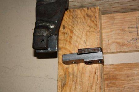
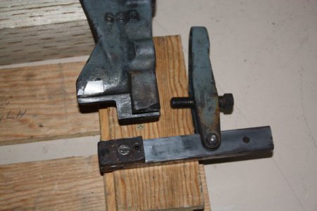
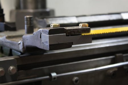
The 90 deg dovetails on the saw frame were badly worn and the mating rails worn out. The OB end of the saw frame was broken and repaired by persons unknown. They welded it back 0.140" offset.
Thats the most significant damage found so far but it's gonna take some time to complete.
Though it's only partially disassembled I have taken some detail pics should you need to see something closer.
Because these have adjustable cutting tension and lift on the back stroke they are top of the line.
Could the repaired offset part be machined straight and shimmed ?
 
The repair also caused a twist at that end of the blade and the groove was welded trapezoid in shape.
I used a cutoff saw in the mill to correct part of the groove but when I got into the welded area it ate the teeth of my saw. GRRR!
Had to finish with a grinder.
I then milled an offset blade holder leaving it about 0.020" thicker than my best measurement where the blade attached.
Put it all back together to confirm the final dimension and took it apart to finish machine.
Did consider cutting and welding the arm but was concerned the material would crystalize.
IMG_9821.JPG
IMG_9820.JPG
 
Here's a view.
View attachment 128349View attachment 128349 View attachment 128350View attachment 128349 View attachment 128350 View attachment 128352
Don't know why the two pics loaded twice.
This has the gearbox. I found three speeds but only saw a six speed listed in the literature you posted. A big thanks for that.
Haven't read all the information yet but it will really help setting up when the saw is ready to run.
The 90 deg dovetails on the saw frame were badly worn and the mating rails worn out. The OB end of the saw frame was broken and repaired by persons unknown. They welded it back 0.140" offset.
Thats the most significant damage found so far but it's gonna take some time to complete.
Though it's only partially disassembled I have taken some detail pics should you need to see something closer.
Because these have adjustable cutting tension and lift on the back stroke they are top of the line.
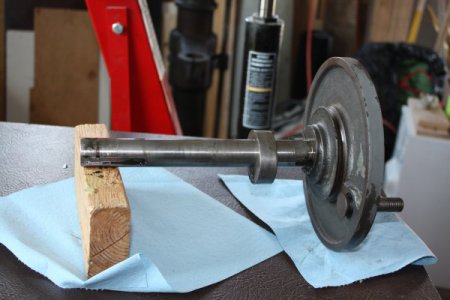
. I will get a picture of the broken end of the saw frame posted. The drive wheel for the saw is another part I would appreciate a picture of. I " think" this saw had a keyway failure on the wheel. It was then repaired with a new shaft and larger key. The wheel also had a crack ( facing the cam) that was reinforced with a machine screw of some type. On the inside of that wheel is The cam that drives the feed and it is pretty loose with about .007 or so slop. That cam is hardened. The part it drives is also worn and equally hard. I will get some pictures up of these as well. I am still atripping parts of gunk and paint. The base is almost ready to paint.
 
These parts don't have any damage that I've found. Must have been quite a wreck to bust the blade frame let alone the other components on your saw.IMG_9823.JPG
 
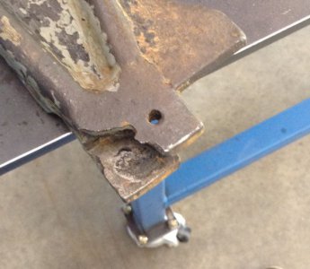
image.jpeg Not sure what happened to this one but maybe there is some lemonade. How loose does the cam fit the shaft? and Pin that ties it together? This is what is broken on the saw frame. What is the T - track groves on both sides of the blade for? Work hold down?
 
There's about 0.005" clearance on both cam fits but the pin is probably a bit offset as there's little movement when engaged.
T-slots are for work holding. A lot of force can be created moving that thick blade through material and some parts might not be held well by the vice.
Here's the offset blade holder installed so both ends of the blade will track the same kerf.
IMG_9814.JPG
 
that is looking good, it should hold good from the looks of it.
 
Thanks!
Would have preferred the ends of the frame line up but after its been worked over once it seemed best to leave it be.
The offset keeps the blade lined up within a few thousanths. I replaced the original retaining pins with larger Dia. ones made of grade 5 bolts.
 
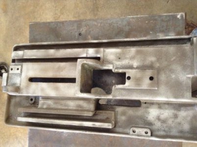
image.jpeg I have checked with a couple welding shops about best path to take and it was suggested by one that the whole end be cut off and a steel one welded on giving it more strength and then remachine the end. This is at a cost of 150.00. The picture I posted is of the saw top or table. Note there is a piece broken off the T track . There is still plenty T track there though so think leaving this alone is best route to take. The piece missing can be seen at the bottom of this puc. Suggestions?
 
I wouldn't worry about the T-slot either.
If a time comes that you do want to repair it, CI can get hard enough to eat HSS when heated so the repair part should be machined and fitted so no further work is needed after welding.

150 bucks would be a big blow to take, especially as other expenses will come up while repairing the saw.
There's been other threads about welding CI and the rods available. Please do a bit of research as you might be able to repair it yourself for a fraction of the cost.
I've had too many irons in the fire and haven't taken notes on the subject. Will probably regret that.
 
Back
Top