New VFD Install

Interesting - so where is that timer in the circuit? Is this to prevent cycling power to the VFD or restricting start/stop commands to the VFD? I was looking through the Huanyang manual to see this auto start delay setting but must not be translating correctly - is there a particular setting for that? If I am drilling some holes or doing some short repeated operations I could see myself starting and stopping within a minute or two of each operation
That was a load/motor issue, not a vfd. We have some at work on an automated polisher that start motor, run for 30 seconds, reverse for 30 seconds, stop for 15 to transfer parts, and do it again all day.

Also, Putting circuit breakers in front of a VFD is always a good idea.
 
In my manual on page 38 it's P1.13 and P1 14. This is only for when power is removed from the VFD. Normally when I'm going to use the mill, I start the VFD in the morning and just leave it on until I go in the evening. Once the VFD is powered on. You can start and stop the spindle as much as you want.
Thanks - also, sorry for hijacking your thread about your awesome setup with my inane questions...
 
Starburst - I am interested in the noise filter application you used. I see you used a three phase model and only used two legs, but have seen others use a single phase model and run 110V through each of the two legs rather than a neutral. Any reason that would not work?

Thanks

Tom
 
Starburst - I am interested in the noise filter application you used. I see you used a three phase model and only used two legs, but have seen others use a single phase model and run 110V through each of the two legs rather than a neutral. Any reason that would not work?

Thanks

Tom
Yes, I purchased a three phase filter because that was the highest amp rated one I could find. From watching a clough42 sp? Video about noise mitigation he said you could use either 3 phase or single phase.
 
Thanks - I will give the single phase a go and should that not do the trick I will get a three phase model. I have most of the components (and found a Hoffman enclosure used on eBay) so I should have something to show in a week or so.
 
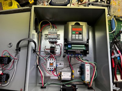
Still have not hooked it up to 220V yet (just got the subpanel installed - still need to run the circuit over to where the mill is). This needs some wire management in a bad way, but I figured I would make sure everything works before I cinch down all the wires. I may do something completely different for the buttons on the panel as that looks messy. Of course, nobody will see it but me, but still. I tested the pushbuttons and contactor using 110V. I used 12ga solid conductors from the fuses to the contactor - I had it on hand and it was easy to bend into shape so I figured why not? (Edit - after I posted this I realized that in this image the 220V leads from the contactor to the filter were not connected - I had taken them off when using 110V to test the buttons. Duh)

I put a little 110V distribution block in there to feed power to the pushbuttons and contactor. I figured something might come along in the future that could need it so I will have it there to tie in to.

I got this Hoffman box off eBay for $100 shipped. It had three holes in the front so I just put a blank in the one I am not using. I sounded out the ground from my plug to the motor, the noise filter, and the VFD ground terminal so at least my grounds are good to go. Hopefully I will have time tomorrow to finish that circuit and bench test the motor and program the VFD. After that it is time to get the motor onto the mill.
Panel rough.jpg
 
Last edited:
Back
Top