That is awesome! Most impressive!
I am planning a VFD upgrade on my HF clone of this mill. I am reading through a bunch of posts here and watching YouTube videos to finalize the configuration of the components, controls, etc and wondered if you had any wiring diagrams you might be able to share. My plan is to include the following:
- Din mounted fast acting fuses on input power
- Din mounted contactor for e-stop
- Forward/reverse control using either existing drum switch or new selector switch
- potentiometer for speed control
- optional tachometer
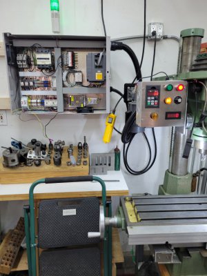
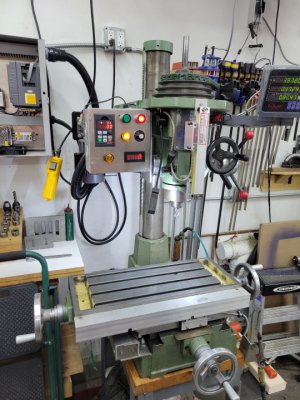
I am thinking I will put the momentary "on" switch on the enclosure door to turn on the VFD and am wrestling with whether to put the e-stop on the enclosure or on a panel at the front of the mill (I replaced the quill scale up front with DRO and have a blank metal plate there now). If the e-stop is on the panel I might have to reach around something that has gone wrong to get to it, so I am leaning towards having it up front. In normal operations I would stop the rotation using the direction switch as that would just stop the motor and not kill power to the VFD (excessive cycling is not good for those devices), but if you know what hits the fan I want to be able to hit the big red button and back away.
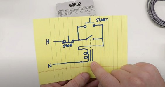
The precise wiring of the e-stop is one of the things that is unclear to me. Where does the momentary switch that tells the contactor to latch draw from - one of the 120V legs of the 220V circuit or a lower voltage source?
I see you have what appears to be an EMI filter inline between the source power and the VFD - I am considering that as well as my TouchDRO will likely not like a bunch of noise.
I know I am asking a lot, but do you have a list of the components you used? There are so many different varieties out there and while there are some posts here that have them some are very old and finding components that were prevalent 10 years ago can be tricky today.
Anyway, your controls look awesome - thanks for sharing!
Tom