New VFD Install

Hello all, thanks for the nice comments about my project.
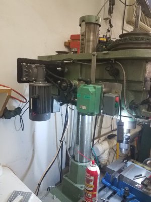
Tomzo, I had to laugh when I saw your post, I struggled with all those things also. Still not sure if I did everything right. And yes I added a gear motor to raise and lower the head. My shoulders are bad and I'm doing all this to allow me to keep working on the mill for as long as possible. So this made the build a little more complex because I incorporated the control of the head into this build.
Unfortunately I didn't do a wiring diagram, I built it on the bench and when I got it working right I installed it on the mill.
I will put together a list of components for you.
The really fun part of this build was the series of relays I used to control the availability of power to the various switches. The lighted switches indicate when a switch is active. So for example, when main power is on at the wall box, the green switch on the operator panel lights because that is the only function you can do at that time. When you hit the green button then the red light comes on, green goes out and amber fwd/reverse is lit. If you unlock the head, the head up/ down goes on and fwd/rev goes out until you lock the head. Very fun stuff.
I use 220v for the VFD, 110v for the gear motor, 24v for the control circuit and 12v for the cooling fan circuit in the wall box.
More to come.
 

Attachments

  • 20210119_083852.jpg
    20210119_083852.jpg
    71.9 KB · Views: 11
Awesome - perhaps I will need a bigger enclosure if I venture into all of those extra features. The component list would be awesome as at least I can get the spec sheets from the manufacturers and plan it out before I get it all on the bench. An electrician is coming tomorrow to give me a price on the new subpanel in my shop, so once I have 220V in there I can start laying things out properly. I just don't want to fry anything along the way....
 
Last edited:
Thanks FireBrick43 - I had planned to use an estop to kill power to the VFD assuming that if my other stop commands to the VFD were not working I had a quick way to kill power to the whole system. It would not go between the VFD and the motor, but be something akin to how Clough42 set up the VFD on his lathe in a video from a few years ago.

I am looking at the Huanyang VFD that seems pretty popular and from reading (interpreting?) the manual I see how to stop the motor - or I guess more accurately take away the run signal. This would trigger the braking system in normal operations it seems to me. I am not planning on a braking resistor right now but that might be something for the future.

I have a pretty good idea in my mind on how this should be wired and was just trying to see if someone had already drawn all this up so I could cross check how I see it being wired against someone's drawing from a working system.

Perhaps it is my lack of familiarity with 220V circuits in this application, but I thought a contactor would allow me to kill both hot legs with one signal wire. If pressed, the estop would cut the current to the coil that holds the contactor closed and that would release all the legs of the 220V circuit going to the VFD. This also prevents the VFD from getting power again until a momentary switch re-engages the coil, thus requiring me to both reset the estop and press the momentary switch to get things going again. Here is a screen shot of how Clough42 set it up.
First I respect Clough42 in many instances, and I have his ELS controller but have not yet gotten around to implementing it yet.

I however disagree with his wiring methods/circuits.

No one runs 110v thru switches any more, and haven't in ages. All the main industrial CNC/automation uses 24 volts. Bring 110v to the panel just adds other safety conserns.

If it makes you feel better, use a relay/contactor to latch in the enable to run circuit, but I think killing power to the vfd is detrimental to safety. None of the machines I work on kill power to the VFD. They do to dumb motors but not the VFD.

I also disagree with his use of insulated ring/fork terminals. Most don't have the proper certified crimpers to do them correctly. Much better is to use uninsulated ones with proper crimpers and insulated with a piece of heat shrink. I have seen to many insulated terminals not crimped correctly and overheat. Same goes for wire nuts on motors.

As for the Huanang VFD, well I refuse to use them. Most of the time I use an AC lenze, mitsubishi, siemens, or minimum teco.
 
I guess on one side of the fence are folks who just plug the VFD into a 220V outlet and on the other side are the people who put different levels of protection between the breaker at the panel and the VFD. You can't get 15A 220V breakers and any 220V outlet will have conductors that are rated for higher amperage than that. The VFD I am looking at is rated at 10A output so if something goes haywire, a bunch more than 10A is going to pass through the VFD. That is where the idea of putting some smaller 10A fuses ahead of the VFD comes in I would think. Since I will likely have the VFD in an enclosure that is likely going to be in a somewhat inconvenient place, I will need a way to turn it on and off, so a contactor with some on/off buttons seems like a convenient way to switch the power to the device from a more accessible location. Clearly, you don't turn it off when the system is running.

With respect to the budget VFD, were I to buy all the name brand stuff I would spend more than I did on this small mill. I got the three phase motor off Craigslist after all, so budget is definitely a concern. I just hate getting out a ladder and wrestling with belts....
 
Hi Tomzo, here is the list of components I used in the build (see attached file).
I was also concerned about cost and sourced most things off eBay and got some really good prices.
 

Attachments

  • VFD Component list.docx
    8.7 KB · Views: 12
Wow - thanks. This is an excellent resource. I see you have a timed relay to prevent the VFD from cycling too quickly. What kind of delay do you have that set for? In my day job I manage a water utility and back in the day when I used to run a treatment plant we used large motors (up to 300HP) and the standard practice was no more than 5 starts per hour. This is just what our electricians advised and I had always thought was a motor limitation but perhaps it was for the VFD.
 
I guess on one side of the fence are folks who just plug the VFD into a 220V outlet and on the other side are the people who put different levels of protection between the breaker at the panel and the VFD. You can't get 15A 220V breakers and any 220V outlet will have conductors that are rated for higher amperage than that. The VFD I am looking at is rated at 10A output so if something goes haywire, a bunch more than 10A is going to pass through the VFD. That is where the idea of putting some smaller 10A fuses ahead of the VFD comes in I would think. Since I will likely have the VFD in an enclosure that is likely going to be in a somewhat inconvenient place, I will need a way to turn it on and off, so a contactor with some on/off buttons seems like a convenient way to switch the power to the device from a more accessible location. Clearly, you don't turn it off when the system is running.

With respect to the budget VFD, were I to buy all the name brand stuff I would spend more than I did on this small mill. I got the three phase motor off Craigslist after all, so budget is definitely a concern. I just hate getting out a ladder and wrestling with belts....
The breaker only protects to the outlet.

The device protects itself.

20 Amp breaker requires correct outlet and number 12 wire.

The VFD should have fuses or beakers inside.

If you want to add protection just order some breakers from Amazon and add them between VFD and cord

Sent from my SM-G781V using Tapatalk
 
Wow - thanks. This is an excellent resource. I see you have a timed relay to prevent the VFD from cycling too quickly. What kind of delay do you have that set for? In my day job I manage a water utility and back in the day when I used to run a treatment plant we used large motors (up to 300HP) and the standard practice was no more than 5 starts per hour. This is just what our electricians advised and I had always thought was a motor limitation but perhaps it was for the VFD.
I'm using 7 minutes, I saw recommendations for 5 to15 minutes, I think 7 should be ok but if anyone has a better idea I'd love to hear it. The Vfd has a built in function for this but it will automatically start after the delay time. I wasn't comfortable with that.
Those timers are vary handy but they take up a lot of space. If you plan on using them layout your Din rail with them installed so you can see how far apart everything has to be.
 
Interesting - so where is that timer in the circuit? Is this to prevent cycling power to the VFD or restricting start/stop commands to the VFD? I was looking through the Huanyang manual to see this auto start delay setting but must not be translating correctly - is there a particular setting for that? If I am drilling some holes or doing some short repeated operations I could see myself starting and stopping within a minute or two of each operation
 
Interesting - so where is that timer in the circuit? Is this to prevent cycling power to the VFD or restricting start/stop commands to the VFD? I was looking through the Huanyang manual to see this auto start delay setting but must not be translating correctly - is there a particular setting for that? If I am drilling some holes or doing some short repeated operations I could see myself starting and stopping within a minute or two of each operation
In my manual on page 38 it's P1.13 and P1 14. This is only for when power is removed from the VFD. Normally when I'm going to use the mill, I start the VFD in the morning and just leave it on until I go in the evening. Once the VFD is powered on. You can start and stop the spindle as much as you want.
 
Back
Top