New shop! (was: Multiple buildings, ...)

Round black nylon puck is a little easier to see here. Rings around the outside of the nylon are from where the drill bit grabbed and it spun in the lathe chuck. 1” diameter center stub shaft from the leg through the caster.
View attachment 409765

My biggest concern with the three legged stand is the granite tipping. Worst case is that I have a little more than 13” from the center mass of the table to the perimeter of the support triangle in the direction of the front corners of the table. The corners are a fraction over 50” from center. So for a 7000lb slab it would take a bit over 2400lbs at the corner to tip it. That is safe enough for human weight ranges to not tip it, assuming I did not mess up my geometry and physics.
Should have known that you had already thought of that. Couldn't see it in the original image until you provided the close up. Nicely done. The airplane tug format will allow you to steer that very easily. Although you may want to rig it with a connection to your three point or a ball if you get a forklift.

I just remembered seeing the granite slab that you purchased way back when. That is a huge slab. Would be a great item to have in the shop.
 
It is not obvious from the picture, but the front wheel pivots on a black nylon bearing. I will need to add some sort of easy way to attach a steering lever, something like an airplane towbar. I don’t foresee moving this very often, it is still going to be a challenge even with the rollers.
Randal, can you add levelling feet that screw down? I find the polyurethane wheels flatten and break apart over time. Mine are not of the same quality that yours are at, but when you want to move it is not the time to find out the poly broke down. Nice design.
 
Randal, can you add levelling feet that screw down? I find the polyurethane wheels flatten and break apart over time. Mine are not of the same quality that yours are at, but when you want to move it is not the time to find out the poly broke down. Nice design.
Good question, I'll have to think about that.
 
Should have known that you had already thought of that. Couldn't see it in the original image until you provided the close up. Nicely done. The airplane tug format will allow you to steer that very easily. Although you may want to rig it with a connection to your three point or a ball if you get a forklift.
That's an interesting thought. I'd figured a heavy rope or chain around one of the legs, attached to the loader bucket was the likely mechanism, as the tractor is big enough to not be generally maneuverable around the shop. That's how I've moved the big lathe and mill, I can then move them somewhat perpendicular to the tractor front/back axis by turning the front wheels (generally in 4 wheel drive).
 
stick a jack under lift it and put blocks under? simple just something to take the weight off them, since it's a tripod it's not going to be twisting .
Yeah, 3 pieces cut off of any of the misc 6"x6" scraps would do. Or I could weld some large nuts on the side of the cross bracess, with 1" all-thread and some feet. Unfortunately that would only work inboard of the wheels, which would reduce stability (tipping of the slab). If I really want to worry about that, the best approach would be to use the jack screws to take up some but not all of the weight.
 
Last edited:
I just remembered seeing the granite slab that you purchased way back when. That is a huge slab. Would be a great item to have in the shop.
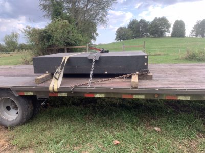
Found the picture. That piece of granite is still sitting on that trailer, could have used the blue gantry to lift it off but have not needed the trailer. Planning on renting a forklift/telehandler next month as will need the trailer to pick up hay.

It will be interesting to see what it would cost to calibrate that slab
279D3088-B7A5-4507-B863-DF8D972A85CB.jpeg
 
Last edited:
Found the picture. It will be interesting to see what it would cost to calibrate
View attachment 409827


I've been watching (as usual) wondering if your intent was to use the granite as a known precision (calibrated) reference surface or not.

The following quote is from Starrett (seems like a reliable source).

"12) How should my surface plate be supported? Does it need to be level?

A) A surface plate should be supported at 3 points, ideally located 20% of the length in from the ends of the plate. Two supports should be located 20% of the width in from the long sides, and the remaining support should be centered. Only 3 points can rest solidly on anything but a precision surface.

The plate should be supported at these points during production, and it should be supported only at these three points while in use. Attempting to support the plate at more than three points will cause the plate to receive its support from various combinations of three points, which will not be the same 3 points on which it was supported during production. This will introduce errors as the plate deflects to conform to the new support arrangement. All Tru-Stone steel stands have support beams designed to line up with the proper support points.

If the plate is properly supported, precise leveling is only necessary if your application calls for it. Leveling is not necessary to maintain the accuracy of a properly supported plate.

Learn more by calling us at (800) 959-0517."


If you intend to have it calibrated (and remain calibrated), my recommendation is to rework the stand to support the granite as Starrett defines.

YMMV

Regarding calibration, I've read of others having a sort of "group buy" situation where geography convenient others bring their plates (with stands as required) to a host location and a Cal service is scheduled in to take care of many in one location. I always liked the idea, for us hobbyists.

Again, YMMV
 
I've been watching (as usual) wondering if your intent was to use the granite as a known precision (calibrated) reference surface or not.
I would like to do so. It was originally a CMM table, so it should be pretty flat. If I do get it calibrated, grade B should suffice, it will not be in a highly temperature controlled environment anyhow.
 
It's been miserably hot here today, 97 today and expected to be hotter the next 3 days. I'm waiting impatiently for my mini-splits to arrive. Ordered and payed for, vendor shows them as "ready to ship" but they've shown that way since middle of last week. Sent them an email today to see what's happening.

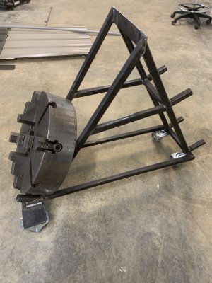
I'm planning on renting a 12,000lb capacity telehandler at the end of the month. Will be using that to move the Monarch 612-2516 lathe, the K&T 3K vertical mill, and the granite table into the new shop. So I'm trying to prep all the little things to go with all of that moving. I have a 18" cushman 4-jaw chuck for the Monarch, as well as a 12" three jaw. I suspect at some point I'll end up with another chuck or two. But the Cushman weighs 260 lbs according to the shipping info so it is definitely NOT a chuck you're going to move by hand. I wanted to get it off of the pallet it has been sitting on, as that pallet was blocking the path between where the lathe will sit and the door. Of course I could just move the pallet, but where is the fun in that? Time to make something! So today's project, including a run to Menard's for the casters, was to make a chuck rack:

IMG_4592.JPG
That's the 18" cushman 4 jaw. Base is 12" wide x 36" long. I wanted the slant rails 12" apart (outside measure) on the back (left) side. The other set of slant rails (over the pivoting casters) are 9" apart (outside measure) to hold smaller chucks, down to 10" diameter. Decided to put the extended tabs on to hold the rear wheels to give it a little wider stance for stability. It should hold 4 chucks when done. Needs another set of stubs to hold another chuck above the cushman, and some cleanup and paint. Probably the one questionable design issue is that if you put only one chuck on the lower front (over the narrower pivoting casters), it could tip if there is no other weight on it.
 
Last edited:
Back
Top