New 1340GT Coming and Need Assistance with VFD

THX for all the input... I am soaking up the ideas.

Gonna re-read all the threads on VFD and the 1340... and make a list of things I want to do... then go back and figure out what parts I need and draw a circuit... I may need some help wiring a latching relay... I am drawing a blank on that... have done it before, just totally forgot how to.

THX to all who are willing to share their expertise and experience.
 
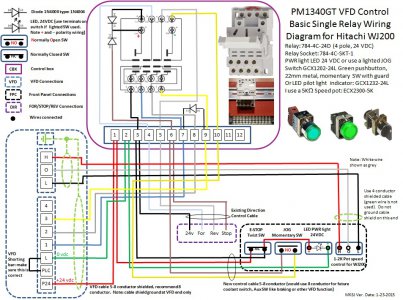
I believe the easiest option is to strip the control board as previously mentioned and put in a 4 Pole relay for simplicity. Anyway you cut it, you need to rewire the front panel switches, it comes out very easy with 4 screws. Once you get things apart, I think it becomes clearer on what to do.Take some pictures and notes as to wiring numbers and location first. I am in the middle of a new VFD build for someone else, but if I get some time in the next couple of days, I will put together a suggested parts list and wiring schematic. Drawing the wiring diagram is a bit tedious because it is done in Powerpoint. I still would give some thought to how/where you want to mount your VFD.
 
Single 4 pole relay VFD schematic for PM1340GT using the Hitachi WJ200. Since I haven't actually hardwired this schematic, I would appreciate if one of the moderators or a second set of eyes could verify the connections. One can also add other control switches and functions, such different braking rates, via a switch that connects the control box terminal 3 to the additional VFD inputs (4-7) and reprogramming their function. The PDF file may have better resolution. Updated speed pot info on 1-23-15.

PM1340GT VFD Control.jpg

PM1340GT VFD Control.jpg
 

Attachments

  • PM1340GT lathe VFD Schematic.pdf
    225 KB · Views: 151
Last edited:
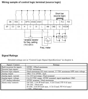
I read previously that a 1k pot was used, but in your schematic you note a 10k. Are they interchangeable, i.e., the VFD is simply looking for a delta V (volts) from 0-10?
 
The previous schematic was a generic copy adapted from on-line, I think they meant 10K as I have seen this in other VFD manuals. The WJ200 manual specifies 10K, I am using a 5K one and it woks OK (the 5K pot is the same value that Matt provided when he sent me my WJ200). Yes it is a voltage divider, but I would not use a 1K, as it increases the current draw as you go to a lower value.
 
Yes it is a voltage divider, but I would not use a 1K, as it increases the current draw as you go to a lower value.

Good point. I'm sure there is a spec on how much this circuit can source current-wise in the VFD's manual, and it may not have protection circuits. Thanks.
 
The previous schematic was a generic copy adapted from on-line, I think they meant 10K as I have seen this in other VFD manuals. The WJ200 manual specifies 10K, I am using a 5K one and it woks OK (the 5K pot is the same value that Matt provided when he sent me my WJ200). Yes it is a voltage divider, but I would not use a 1K, as it increases the current draw as you go to a lower value.

What is weard is two separate places in the manual the pot specs vary. In the schematic it seems it mentioned 1k ohm and in the literature it mentioned a 10k ohm, or the other way around I can't remember.

I am using a 1k ohm and it works perfectly. For a control circuit it isn't going to matter much as there is not much current to begin with. The sensitivity of the pot is what would be affected by the ohm difference, it is merely adding or subtracting resistance.

Mike.
 
Once I hear from Matt that the lathe is on it's way (just to make sure...) I'll start ordering the stuff in the first part of this thread like the relay, relay socket, diodes, cables, etc.. I'm also going to get a machtach to put on the spindle so I have true spindle rpm rather than a guess on my part. :)

I'm wondering if I can replace the electrical box on the lathe with the NEMA one that is recommended also. This would make it easier to mount the VFD on the lathe and make it semi-portable for when I do move. :thinking:
 
I'm wondering if I can replace the electrical box on the lathe with the NEMA one that is recommended also. This would make it easier to mount the VFD on the lathe and make it semi-portable for when I do move. :thinking:

No real need to keep the current lathe control box if you mount a VFD cabinet to the lathe. Just be sure to not leave out the old mounting screws, and put a little sealant on them when you put them back in (the holes go through into the gear box). You may want to keep the old transformer or replace it with a PWM supply if you use the 24V light. If you mount a DIN rail in the new box, it makes it easy to mount relays, power supplies and breakers if you go that route.

I stand corrected on the speed pot, input impedance is 10K, the WJ200 manual specifies a 1K or 2K potentiometer. Matt sent me a 5K, which works fine, use what you want. The bus input is rated to 100mA. It is one reason that I specified a LED power indicator light, between the relay and the LED your are drawing around 90mA.

WJ200 Signal Ratings.jpg

WJ200 Signal Ratings.jpg
 
I was thinking of replacing the contactors with the 4-pole relay, and keeping the existing 24v transformer and switch hardware. Then just rewiring what needs changing.

Should I get a DIN mount, or just move things over from the existing electrical box to the NEMA? (sorry for the ignorant questions, but I did warn everyone... :whistle:)
 
Back
Top