New 1340GT Coming and Need Assistance with VFD

Just got an email from Nicole saying the machines will be in by Friday. Now the wait for setup & testing (fitting the DRO on mine too) plus the shipping all the way back across the country :impatient:

Meanwhile I'll call Matt & ask his price on another Hitachi VFD. Can get one for $313 online, but maybe he'll make me a swingin' deal. Can't hurt to try.
Anticipation time, for sure!
 
"Dusting off" may be a bit of a misnomer, as I had to ask what a contactor is... :dunno:

I'll muddle through this somehow. With help from my online friends. :) Lots of great info here, just need to figure out what I want to do and how much of this applies.

For example: Mark used 12G cable to the VFD and only 14G to the motor. 14G is smaller, right? I'm a bit confused on that. And it gets worse from there... :lmao:
 
Just got an email from Nicole saying the machines will be in by Friday. Now the wait for setup & testing (fitting the DRO on mine too) plus the shipping all the way back across the country :impatient:

Meanwhile I'll call Matt & ask his price on another Hitachi VFD. Can get one for $313 online, but maybe he'll make me a swingin' deal. Can't hurt to try.
Anticipation time, for sure!

Sounds awesome. Getting closer at least.

I would definitely check with Matt about the VFD he can beat that price. When I ordered mine from him the VFD actually showed up several days ahead of the lathe which allowed me to get it wired into the NEMA enclosure before the lathe's arrival. Not a big deal, just one more little detail that I was able to get done before the lathe showed up.
 
"Dusting off" may be a bit of a misnomer, as I had to ask what a contactor is... :dunno:

I'll muddle through this somehow. With help from my online friends. :) Lots of great info here, just need to figure out what I want to do and how much of this applies.

For example: Mark used 12G cable to the VFD and only 14G to the motor. 14G is smaller, right? I'm a bit confused on that. And it gets worse from there... :lmao:

I think I can help you with this one...

Wire gauge is related to amperage. The more amps, the lower the gauge number.
14GA = 15 A
12GA = 20 A
10 GA = 30 A
8 GA = 40 A
6 GA = 55 A This one is questionable...
etc.

Given the same load; the actual amperage used by a 3PH motor will be lower than a single phase motor... three wires rather than two, and the motor is more efficient. (Yeah, not a very techincal explanation).
Thus the amps flowing to the same load; from the supply to the VFD, will be higher than the amps from the VFD to the motor.

Now if we want to talk about protecting the wire with a circuit breaker... then perhaps 12 GA at all locations.

Does anyone know if the VFD actually regulates the amps as well as the phase?


The part I am gonna have issues with... is sorting out the programming of the VFD. Reading all that stuff, my brain tends to scramble.
The wiring, if I stare at it and think about it (and doodle on a yellow pad)... it will make sense and come together.
 
Does anyone know if the VFD actually regulates the amps as well as the phase?

The part I am gonna have issues with... is sorting out the programming of the VFD. Reading all that stuff, my brain tends to scramble.
The wiring, if I stare at it and think about it (and doodle on a yellow pad)... it will make sense and come together.


The VFD does regulate the current to some degree by regulating the voltage. The VFD will protect it's self and the motor by current limiting if the case of an overload or other fault.

The programming is not too terrible, normally you only need to change a few settings to be up and running. We can help you through it.

THX, appreciate that!

I am starting to visualize the features I want to wire in and program... When I have that ready, will be time to start 'doodling' on paper.
 
The motor nameplate amperage is 6.6A, the NEC 460 wiring guidance for 3 phase is as follows:
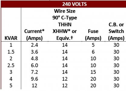
Wire size for 3 phase per NEC 460.jpg

Unless you have long distance between your VFD and motor (not recommended) then 14G (3 wire + ground) is fine. The VFD regulates it's output and will shut down if it exceeds it's programmed limits. Going from the VFD to your breaker box/outlet, 12G is rated to 20A (single phase), so would be OK for distances up to ~25', otherwise 10G. It is also recommended to fuse the VFD with a 30A cartridge or suitable breaker. Breakers are available with different overload characteristics, so either a C or D curve. Since the VFD's have soft starts, you have reduced inrush currents and less likely to trip the breaker. If you have a service disconnect switch before the VFD, a 25-30A rated switch should be fine.

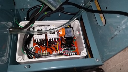
Mike outlined the connection schematic for the PM-1340GT. The easiest build is to remove the existing control board, strip out the contacters and relay (just keep the 24VAC transformer for the light) and keep the barrier strips. Note the current control connections. Mount a single 4 pole relay to the board, and connect per the schematic. I can make up a diagrammatic picture/relay connections and parts list if needed. Just be aware that when a relay is mounted to a socket base, that the socket terminals are in a different location then the relay itself.

Also you need to decide if you want to use the current front panel switches or upgrade them. Regarding the VFD, you need to decide where you want to locate it, and if your going to use an electrical cabinet and adding a breaker/service disconnect.

This is a great VFD enclosure at a very reasonable price: http://www.surpluscenter.com/Electr...s/LARGE-WHITE-ELECTRICAL-ENCLOSURE-1-4703.axd

You need to add a cooling fan, and some form of service disconnect. If you not familiar with mounting circuit breakers (I use DIN rail types), I would just use two 30A cartridge types in the enclosure (Like in Mike's enclosure). I recommend shielded wire between the VFD and the speed pot, and the VFD and the barrier strip. It is also recommended between the motor and the VFD, but not a deal breaker. The shields should be grounded at the VFD (not both ends), but you must run a separate ground wire to the motor. I use a single screw post in my VFD cabinet to tie all the grounds together.

Regarding programming the WJ200 VFD, I previously outlined some recommend parameters for this machine. This is a good starting point, I recommend programming in steps so you can figure out if you did something wrong.

Wire size for 3 phase per NEC 460.jpg
 
Honestly? I just want to replace the single phase motor with the three phase and wire it to the VFD. That is probably over simplistic, but you get the idea.

Right now, I'm not interested in replacing any of the front panel controls or added new ones. Maybe later. :)

But if I'm hearing you correctly, you are saying replace all of the existing controls/contactors with that available on the VFD?
 
You use all your current switches on the lathe. So there are two possibilities to control the VFD commands. The first is to replace the contactors and the power relay with a new single 4 pole latching relay and wire per the schematic. The second option (and I need to give this some further thought), is to use the current contactors (as your For/Rev) relay commands to the VFD. All you would need to do is remove the high voltage wiring to the two contactors. The Jog switch would need to be rewired directly to the VFD inputs, so when it is pressed, it would send the Jog signal and the forward command to the VFD (you need to add diodes to the current switch or change it out to a dual NO contact switch).

In either case, you would probably want to use an external speed pot, this comes with the VFD or I have some spares I can prewire and drop one in the mail (mount it in the coolant hole). I could come up with a revised wiring diagram/directions if you want to keep the contactors, but I couldn't test it on mine. I actually used the old PM1340 control board and contactors in my bandsaw in a similar arrangement (just no VFD), I wanted low voltage switches.


Bandsaw with PM1340 control board.jpg

Bandsaw with PM1340 control board.jpg
 
I'm starting to think I should replace the contactors with the 4-pole relay in order to keep things as simple as possible. :)
 
Back
Top