Needing more than a spark test?

Regarding the question about the availability of the X100-7 x-ray detector, I found that Sparkfun has discontinued it. Robotshop.com claims to carry it, but it's currently backordered -- and the source is Sparkfun, so availability there is a strong "maybe not". They also are asking $91.25 not including shipping.

Interestingly enough, Mouser offers a version that includes a CsI(Tl) scintillator. The scintillator bumps the price up to a bit less than $124 -- and it's currently backordered. The X100-7 w/o a scintillator is no longer available via Mouser.

As a potential alternative, I note that Mouser has a number of SiPM detector chips. They have a 3x3mm for $29.21 and a 4x4 for $34.70. Combine that with one of these and you've got a more mainstream type of detector for less than what I paid for my pocket geiger. This particular CsI(Tl) crystal already is coated with highly reflective paint to direct more photons into the detector. The front end electronics would be very similar to what's been discussed for the X100-7, including the bias generator.

These SiPM's come in micro BGA packages, which would be an issue for many DIYers. But the parts supplier arm of EasyEDA offers the 3x3, which means that interested parties could order PCBs that already have the SiPM installed. They do tack on an additional ~$5 compared to Mouser but that's cheap compared to the base price if you screw it up....
Well that's discouraging. Still have my Sparkfun module, but that won't help anyone else.
 
Well that's discouraging. Still have my Sparkfun module, but that won't help anyone else.
There are a number of larger-area PIN diodes out there but I'm not aware of any others that are specified for use as x-ray detectors. At least, none that are halfway affordable.

A company called Amptek sells an x-ray detector module that uses a silicon PIN photodiode cooled by a 2-stage Peltier. It is a 6mm^2 detector so far smaller than the X100-7. This doesn't mean that any old PIN photodiode with comparable area would work. The important thing is the width of the intrinsic region, where the x-rays produce hole-electron pairs. Wider is better, so if diode A has lower capacitance than diode B (under reverse-biased conditions), diode A would be better suited as an x-ray detector.

That said, a quick comparison of the capacitance/mm^2 of the X100-7 and a 7.5mm^2 PIN diode (the Vishay TEMD5080) shows a significant difference between them -- about .5pf/mm^2 vs. 2pf/mm^2 for the Vishay device. That might be a bridge too far in terms of usefulness as a direct-conversion x-ray detector.

BTW I have ordered one of the CsI(Tl) scintillators I mentioned.
 
@graham-xrf , half decent crystal oscillators are available for not too much cash. We used them in automotive radars, so they had to be very inexpensive. We used 16 bit converters. Although ADC's are sensitive to clock noise, quite often, it is usually not the clock which is the dominant noise contributor.

Often it was a poor front end, or even sloppy signal processing that lead to the classic, "we are 10 dB worse than we ought to be". (I've seen far worse on some systems.) Obviously, not saying something you don't know, but thought I'd point it out to others (if anyone is still following). I've had many occasions to install extremely low phase noise oscillators into systems and saw no difference. It should have helped, in theory, but the dominant noise contributors were far, far greater and swamped the contribution of the oscillator, so there was no detectable difference, even in a statistical sense over > 10,000 trials. In one case, it was a bitter pill for the software team to swallow, since in fact it was their algorithms that were degrading the SNR, not the oscillator. Once those algorithms were identified, they were changed and we achieved predicted performance.

An ADC triggered synchronously via a quality time base, typically a crystal oscillator, with quality clock drivers, usually gives very good results. If a processor triggers it, well that's really not going to work. The data collection can be processor driven, and have some jitter, but not the trigger. Some processors even dither their clock, so they will pass emissions standards, the dither simply introduces noise into the trigger, which in turn injects noise into the sampled data.
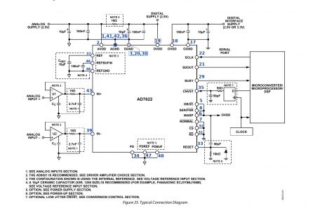
OK - I think you are right, and looking again at the Figure 25 from the data sheet, see the special arrangement at lower right that has the optional low jitter clock.

AD7622 Pi3 pins.png

If the processor also gets to use it, that can be a bonus, but done in the way shown, no common mode energy makes it from the processor to anywhere except OVDD, and we strive to make it clean anyway. If some little package ready-made clock can be had at reasonable low cost, and it has fast transitions with low phase noise, then that seems a convenient way to go.

In my now previous career, coming after extremely low noise coupled with large signal handling capability in front ends, phase noise performance from the oscillator to the first mixer was the thing that determined performance. However sharp it looked on the spectrum analyzer, way down near the noise floor, was always the little lump of spectrum spread that came from phase noise.

I would not be too wound up over available X100s. The suggestion from @homebrewed about alternatives is OK, and we may yet stitch together any of all sorts of handy getups we may find later. The basic circuit will work with all.
 
Last edited:
@graham-xrf , half decent crystal oscillators are available for not too much cash. We used them in automotive radars, so they had to be very inexpensive. We used 16 bit converters. Although ADC's are sensitive to clock noise, quite often, it is usually not the clock which is the dominant noise contributor.
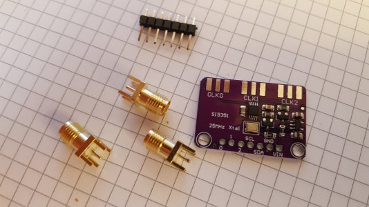
Do you think one of these might do the trick?
SI5351 Clock Kit.jpg

For us, it is not needed to have amazing accurate ppm frequency stability, so much as regular pulse edges that do not have slightly uncertain transition instants that come from uncertain turn-on thresholds in the devices that make the pulses. There is a whole (very expensive ICs) science to "jitter cleaners techniques", specialized clock ICs and clock distribution, none of which we really need.

These seem to need a little initial I2C configuration to set the frequency. Maybe a more straightforward little crystal can TCXO would be better.

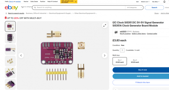
I had the little kit laying around for ages, so now, it might become useful. The SI5351 claims typically 30pS cycle to cycle jitter on clock rise and fall times of typically 1nS. One thing - these kits are CHEAP! Why else would I have some just "laying around"?

Si5351 Clock Kit2.png

For convenience, I have attached the datasheets.
 

Attachments

  • Si5351.pdf
    487.9 KB · Views: 2
  • ms5351m.pdf
    476.4 KB · Views: 2
Last edited:
We looked at this class of devices quite a while ago, characterized them and concluded they were not suitable, ie good enough, for our automotive radars. On the surface they are quite attractive, but we found simple crystal oscillators were better performing, more reliable and in high volume less expensive. Automotive qualified parts were effectively MIL spec and they had a huge paper trail just like I remember military parts had.

Maybe they are better now, but these nuances were only truly apparent under system operation by effectively using the high gain of the receiver to detect this stuff. It wasn't apparent from direct measurements of the oscillators, nor from the specifications. This is reaching back, but I seem to recall something vaguely about deterministic noise from the internal PLL of the "oscillator device". The nuances or complexities took it out of the running for us. A simpler lower complexity device was chosen instead.
 
The Si device is what we evaluated. RMS jitter is only integrated over a limited range, I think up to 20MHz which entirely discounts noise above that. That's not good enough, at least for radar.

The other part seems to be a knockoff of the first but with even less documentation. Specs are a bit worse as well.

You will notice with both there's no phase noise plots or graphs to do any evaluation. I'd pass on both unless we have a spec operating system to swap it into. Stick with non PLL crystal oscillators for sampling analog data. You asked what I thought, so that's my experience with these, for what it's worth.

A straightforward crystal little external oscillator circuit, with some help from a very fast logic back end might be all that is needed. Traditionally, adding some positive feedback Schmidt trigger is how they made square waves, sometimes using a cross-coupled divide-by-two to end up with 50% duty cycle square waves

A single transistor or JFET can do the oscillator part. Here is where handy information gets sparse.

You can get lots of very informative stuff on YT from FesZ Electronics with keyword "crystal". Everything you could ever want to know about characterizing crystals, modeling them in LTSpice, and measuring on them to discover the parameters, and incidentally sometimes using kit that most of us can't afford, but never going into an actual oscillator other than one built around the CMOS two-inverter scheme that is built into most little things you just add a crystal to. My best cheapo one-transistor hacks have produced quite low distortion sine waves of several volts, which become pristine if they go through the crystal filter. These are great for receiver mixers, but lack the "squaring" with constant threshold low jitter. This would be the first time I tried for classy A-D conversion, but I admit I was hoping for something fast and cheap that "just works".

One can get crystal versions of all topologies, like Colpitts (parallel),or Pierce (series), or Clapp, etc. Some of the versions that exploit logic inverter gates that use a first inverter to be the oscillator with 180° phase shift, the rest provided by the capacitors, and the other inverter provides the full logic transition "squared-up" output, relying on the inverter input threshold. Others use two inverters in series to get the whole 360° out of gates. Then there are the usual pins provided on microcontrollers to fit a crystal, or not, or have an external input.

Crystal oscillators in little flat cans can get expensive. Regardless, one of these cheap hacks may be good enough, or maybe some little scheme I dream up.
 
SMT oscillators are inexpensive, so perhaps something like this might be more suitable. I just looked this up on Digikey. https://www.digikey.com/en/products/detail/abracon-llc/ASE-50-000MHZ-L-R-T/2637780 Yes it is tiny! 3.2x2.5 mm.

5ps RMS jitter, don't know if it is great, but this is a $0.79 USD part (quantity 1) with 3.3V CMOS output. According to the data sheet they offer lower jitter parts (at a higher price). Yes, it is fixed frequency 50MHz, but that's pretty inexpensive. It would be worth a try, if the frequency was suitable. I'm sure there are better units out there for not much more. There's no phase noise plots, but maybe they have an app note, or could supply one. But I'm fairly certain that it will out perform the Si5351 for sampling ADC's at high frequencies. And there's no software to deal with... Apply power and it just runs.

Having designed some special crystal oscillators in the past, I'd much rather just get something like the above 79 cent unit. We probably don't need an infinite number of rabbit holes to fall into... You are free to disagree of course, but I think it would be better for this project to refocus on the main task. This thread is pretty old, none of us are getting any younger and an affordable XRF solution has yet to be realized.
 
Having designed some special crystal oscillators in the past, I'd much rather just get something like the above 79 cent unit. We probably don't need an infinite number of rabbit holes to fall into... You are free to disagree of course, but I think it would be better for this project to refocus on the main task. This thread is pretty old, none of us are getting any younger and an affordable XRF solution has yet to be realized.
Yep - I totally agree. I would go for the little crystal. Re: what we have been exploring, I never thought I would go here, and I always knew I was into something that did not have a fairly logical path through known technology involving stuff I could do.

There has also been a phase where I was looking at not being able to do any of it at all! Medical technology has somewhat rescued things, and I have returned to (sort of) normal, which is why I am dabbling a bit again. This year, while I am able, I plan to travel to the other side of the planet, and finally visit my family. Meanwhile, if I get anything to XRF work, even in a incomplete way, I will let you know. I am OK to be with the very old thread for now. We want something tangible, with real results shown here, before we start a new thread - if we get the chance to.
 
@graham-xrf The device I linked earlier was a self contained CMOS crystal oscillator with tri-state output. Everything is integrated into the 3.2x2.5mm package. It only needs a capactor across Vcc and power to run. Nothing to cobble together or tweak. For 79 cents, and 5ps RMS jitter, it would be hard to beat.

Think it would be good to keep everything about XRF in one place :) No need to make additional threads, in my opinion.

Glad to hear you are on the mend and able to get about again. May you continue to improve.

FYI, I was able to get an RPI5 and attach an NVMe SSD to it. It's not equivalent to a modern PC or Mac, but it is very serviceable and has good performance, especially considering cost. It does require a fan, which could make packaging a little awkward. At rest, the heat sink is warm, maybe 40-45C. The fan module is $5 USD which is a bargain compared to what it would cost to make yourself. The RPI5 uses a built-in PWM fan algorithm to regulate the temperature. As I recall, you were tinkering with an RPI for interfacing and processing purposes.
 
Back
Top