Need to fix an eff up, can I fill a hole in cast iron with silicon bronze?

Looking at your figures, I would just increase the length of the slots and move the hole locations. I generally like to have a hole located a minimum of a hole diameter from an edge. In the case lof threaded holes, that would be the o.d. of the fastener. If it were me, I wouldn't bother plugging the defective holes. It's only cosmetic and they are hidden from view by your mounting plate. If you must plug them, use mild steel and Loc Tite.
 
Thank you for the 3D rendition, it seems I was seriously mistook about what you were trying to do. It looks like, if things will clear, you can drill new holes(slots) in the adaptor plate that are offset from the original mounting holes. Then abandon the mis-drilled holes, not bothering to fill or hide them. Clearance for the offset fasteners would be the big issue, making sure the adaptor plate was accessible.

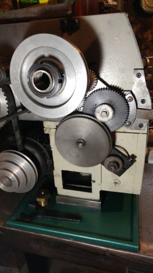
From an earlier photo, it looks like the machine is at least the same general shape(?), form factor(?), whatever as my Taiwan made Grizzly 9 inch. If so, there are some sheet metal covers over the motor area that can be removed, giving good access to the back of the frame. It involves removing a few fasteners but nothing that will change the "character" of the machine. The basic idea being to get the electrics enclosure out of the way so drilling will be true.

.
The Grizzly G0602/G0752 is totally different than the G4000. The base casting is solid at that point. Access to the electrical system is at spindle level.

ELS Mod .JPG
 
if the aim is to use the mounting points to tension the belt, I would suggest a single round hole as the pivot point and a slot (curved or a straight and a bit wider than normal) to allow the bracket to swing. If the belt goes from bottom left(ish) on the motor to top right(ish), then having the pivot hole at the top left of the bracket, looking at the gears, will allow the weight of the motor to pre-tension the belt. Then you only need to snug up the bolt in the slot.
 
if the aim is to use the mounting points to tension the belt, I would suggest a single round hole as the pivot point and a slot (curved or a straight and a bit wider than normal) to allow the bracket to swing. If the belt goes from bottom left(ish) on the motor to top right(ish), then having the pivot hole at the top left of the bracket, looking at the gears, will allow the weight of the motor to pre-tension the belt. Then you only need to snug up the bolt in the slot.
At this point, I am more or less committed to what is there. There really isn't quite enough vertical room to pivot enough to snug up the belt. I had to grind out a lot of material by hand to even get the motor body to fit at all. There is about 1/4" of vertical free play before the motor hits the lathe casting. I'll just slightly lengthen the bottom slots, attach the drill bushings to the plate and drill new holes.

If I were to do it all over again, maybe I'd approach this differently. Certainly the hole drilling didn't go according to pln!

I'm really happy, no delirious, that the motor fits the steel plate, the motor screws in correctly and the spacing came out right. Oh, and the belt length is darned close to perfect.
 
The Grizzly G0602/G0752 is totally different than the G4000. The base casting is solid at that point. Access to the electrical system is at spindle level.

View attachment 419513
As an aside, my Grizzly "predates" the G-4000 by a few years. Your comment is acknowleged, just not quite accurate by a couple of years. While the G-1550 is almost the same as a G-4000, it should be differeniated by at least quality/accuracy.

.
 
Another "idea" to consider.

First, consider the "sloppyness" of the slotted holes.

So here is a thought.

We will assume you can get to the back side of the lathe base.

Looks like the plate has some thickness to work with.

On the back side of the plate mill out a slot directly behind the slotted screw holes.

The slot is same size as a rail that you make, as an example, 1/2 inch wide by 1/4 inch thick.

Now. The rail will have the 2 bolts as countersunk screws forming studs.

The rail is secured to lathe by several SMALLER flat head screws, 10-32 are a good size, the lathe can be tapped so the screws attach via those threads or nylocks used on the back side.

Bonus option, on the end of the plate in alignment with the slot drill and tap a hole in alignment with slot.

A screw here will push against the stud to keep the belt tight.


Sent from my SM-G781V using Tapatalk
 
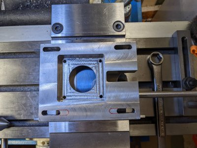
Removed the motor from the plate. Have the plate in the vise ready to enlarge the slots.
PXL_20220907_131025567.jpg
Probably lengthen the slots another 1/2" or so. Think that should give me a full screw diameter of spacing of the bum holes in the lathe casting.
 
that makes sense, I did wonder if you'd have enough room for the motor to swing to tension the belt.
 
that makes sense, I did wonder if you'd have enough room for the motor to swing to tension the belt.
Practically speaking there is no room to swing the motor. Translation along the slots is how I have to go. If the motor drops about 1/4" vertically I foul with the bolt head holding the lathe. It's a tight fit inside the ways casting.

I can't quite install the belt if the motor is in place and the plate is fastened to the lathe. However if I loosen the slot bolts, I can just wiggle things enough to get over the lips of the timing pulleys. About a 1/4" movement along the slot length snugs up the belt nicely. Sort of lucked out calculating the belt length, got this belt length right the first time.
 
Slots are lengthened on the bottom by 1/2" towards the center. Waiting for some 1018 stock to be delivered today to make the weldable drill bushings.
 
Back
Top