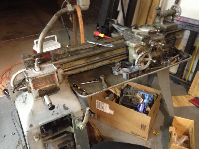
My Heavy 10 Rebuild

Nice job on the steady rest! Do you mind sharing what you paid for the unit? I am looking for one, it seems that most are 9" and I see very few heavy 10's to get a good idea on pricing.

Hi there,

I found this lathe on CL, the guy wanted a grand for it, and I gave him an extra 100 for helping me load it. Given the condition, I thought it was a fair price.

Thanks for the advice on the QC toolpost, ordered one today!

As for progress, I didn't get to the QC gearbox like I was hoping, but I did get some more cleaning, stripping and painting done.
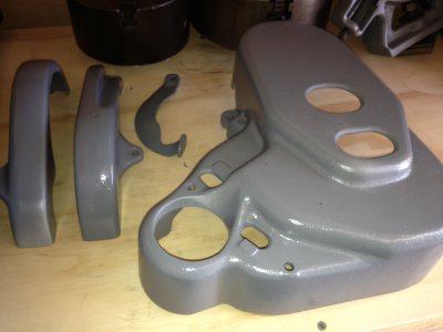
Photo Jun 01, 1 09 38 PM.jpg
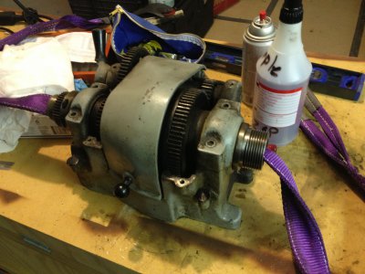
Bull gear guards, and access door, as well as the gearbox cover all done.

Also took apart the three jaw chuck, it was difficult to move, found about pound of dirt and shavings. Once cleaned and greased, moves like a dream!

And a question for Heavy 10 owners, how tight are the cap screws on the spindle bearings supposed to be? I took one off to see the condition of the bearings, and when I re-assembled it, with the shims in the right places, and found I couldn't turn the spindle. After some analyzing, to make sure I wasn't being dumb, I started to take the caps off again, which immediately freed the spindle. After some playing, I find that the screws cannot be tight, as in make them hand tight with an allen key, and back it off 1/8 turn. Does this mean that I am missing shims, or is this just a strangeness of an old machine? There is no noticeable play in the spindle in this state, but it doesn't seem quite right.

Until next week,

-Cody

Photo Jun 01, 1 09 38 PM.jpg
 
And a question for Heavy 10 owners, how tight are the cap screws on the spindle bearings supposed to be? I took one off to see the condition of the bearings, and when I re-assembled it, with the shims in the right places, and found I couldn't turn the spindle. After some analyzing, to make sure I wasn't being dumb, I started to take the caps off again, which immediately freed the spindle. After some playing, I find that the screws cannot be tight, as in make them hand tight with an allen key, and back it off 1/8 turn. Does this mean that I am missing shims, or is this just a strangeness of an old machine? There is no noticeable play in the spindle in this state, but it doesn't seem quite right.

Until next week,

-Cody
You are missing shims. A lift test with a dial indicator is needed to properly set the clearance. The screws should be equally tight. If the clearance isn't right the spindle can be starved of oil, and you know what that means can happen.
 
Hey Greg,

I guess this means they were missing when I bought it, as I was VERY careful to keep them all together when I removed the caps.

With that, do you know of a source for the shims?

And the lift test, I am imagining the following.

Add shims until I am able to get movement up and down on the spindle.
Setup the dial indicator set of the top of the spindle, and lift up by hand on the spindle.
The difference in position is how much shim needs to come out?

I guess I am in need of some help here.

Thanks in advance!

-Cody

- - - Updated - - -

A search answered my second question.

http://www.hobby-machinist.com/showthread.php/710-heavy-10-spindle-bearings

-Cody
Yup, and if you only need to make a few shims you can trace a pattern of a good one on some brass shim stock and just cut them out with a pair of sharp scissors. .001 or .0015 brass shim stock will cut easy. I can't remember but I think I showed the set up for doing the lift test in my rebuild thread. A solid steel bar is great for doing the lift test, I used about a 3 footer for leverage. Take your time on this step and get it right, it's very important for proper oiling of the spindle, good cuts, and long life of the spindle and bearings. I don't know of a source for shims, I even checked with grizzly/south bend, most people just have to make their own now. Each time shims are added or removed a lift test needs to be done, make sure the spindle and bearings has oil and spin the spindle by hand to make sure it is free and not binding anywhere in it's rotation. Also when you are satisfied with the set up run the lathe at different speeds for awhile and touch the bearing caps to make sure they are not getting hot, a little warm is ok but not hot.
 
Hello again,

Greg, thanks for the info on the shims. It will be a while before I get to that stage, but its good to know beforehand.

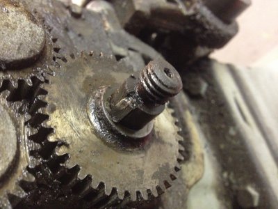
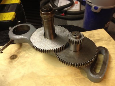
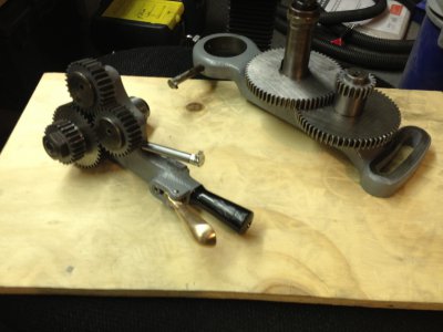
Started disassembly on the gear train last night, got everything apart without damage. Though it looks like it was damaged before... (The photo doesn't read well, but the top right corner of the key is chipped! Hate to think someone slammed it in with a hammer!)

Photo Jun 02, 11 39 45 PM.jpg

The shaft that supports this gear, the reversing gear, was also brazed partway around, as well as one of the other shafts, with brazing all the way around. No breakage that I could see, simply looked like wear.

I was a bit confused by some of the steps in the rebuild manual, regarding the wicks. I eventually figured out that my lathe is old enough to not have some of the oil ways and feed tubes that the manual refers to. Instead of wicks feeding other wicks, the oil needs to be applied to individual gears, or rather their shafts, through the small oil hole located in each shaft. Cool, but had me confused for a bit.

Anyone know where I can find the extended oil tube for the reversing gear assembly? The cap was missing when I bought the lathe, and I'm having trouble finding a source for them. If I can't find it, I'll just get a short one, and make a extension tube.

Hopefully tonight I can get the geartrain cleaned and re-assembled tonight, and move on to dis-assembly of the QC Gearbox. Which of course means removing the head-stock. Fingers crossed, everything will go smoothly!

-Cody

Photo Jun 02, 11 39 45 PM.jpg
 
I found the same thing with the wicks, my reverser was different as well and did not have all the plugs and wicks that the manual described. Most things where right on except the wicks. There are many variations of these lathes.
 
You will enjoy the labor when you are done. Don't rush it. May take 3 months, may take a year....but just be careful and do it right. Your Lifetime of enjoyment awaits! Degreasing, cleaning, and paint prep take a good portion of time. The FUN begins when you paint and see all these old parts look like NEW again. Enjoy the assembly process, We all learn how lathe works by taking it apart and fixing. Lookin good!
 
Boy was it a busy weekend!:whiteflag:

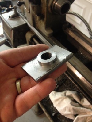
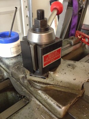
First, AXA QC Toolpost arrived. Lacking a milling machine to make the T-Nut, I attached the 4-jaw chuck and dialed it in to the center post.
Photo Jun 12, 1 24 22 PM.jpg
Mounted in its new home.
Photo Jun 12, 1 22 44 PM.jpg

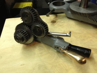
I machined the T-nut freehand, well without power feed, because I disassembled the geartrain to restore it! Finished that this weekend, been painting a little bit here and there through the week. I couldn't find a new extended oil fill tube, so I made one on the mini-lathe, as shown in the following photo.

Photo Jun 15, 1 16 47 AM.jpg
Photo Jun 15, 1 16 51 AM.jpg
Photo Jun 15, 1 16 41 AM.jpg

I then continued on with the restoration, according to the rebuild manual, with the QC Gearbox and leadscrew. In order to do this on my lathe, I first removed the headstock, after I found the bolts under about 70 years of crud! After that, it was a simple matter of three screws, and out it came. (Its about 5 pounds lighter now that i have removed all of the chips, oil and grease caked in there!)

Headstock removed for access to the QC gearbox screws.
Photo Jun 14, 9 52 09 PM.jpg

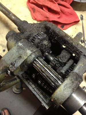
QC Gearbox removed and on the bench for cleaning, and BOY does it need it!
Photo Jun 14, 10 18 46 PM.jpg

ITS A HEADLESS LATHE!!!!!
Photo Jun 14, 9 52 04 PM.jpg

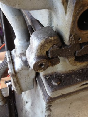
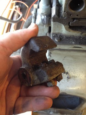
When I went to remove the headstock, I found this part clamped to the rear V-way, behind the headstock. Looks like it was painted in there! Thought at first it was a carriage stop, but it doesn't line up with the pad on the carriage. Any one have a part like this, and if so what exactly is it?

Photo Jun 14, 7 25 45 PM.jpg
Photo Jun 14, 7 25 54 PM.jpg

I also got the gearbox disassembled and cleaned. I was expecting trouble from the cone gears, can't say I had NO trouble, as one taper pin did not survive, but it was the clutch parts that gave me hell! In the end, the felt that was in the gear with the tangential pin, gummed everything up when I tried to slide the shaft out past the pressed on gear. But no harm done.

Well that's it for now, I should have more progress in a couple of days.

-Cody

Photo Jun 12, 1 22 44 PM.jpg Photo Jun 12, 1 24 22 PM.jpg Photo Jun 14, 7 25 45 PM.jpg Photo Jun 14, 7 25 54 PM.jpg Photo Jun 14, 9 52 04 PM.jpg Photo Jun 14, 9 52 09 PM.jpg Photo Jun 14, 10 18 46 PM.jpg Photo Jun 15, 1 16 41 AM.jpg Photo Jun 15, 1 16 47 AM.jpg Photo Jun 15, 1 16 51 AM.jpg
 
That part in question is what the sliding gear banjo attaches too. A bolt goes through the long arked slot and into that clamp, it is so the clearance of the gears can be adjusted, and is an anchor point. A very important part.
 
Right. Duh.

Guess the cleaning solvent fumes got to me, now I remember taking the bolt off of there. Hmm.

-Cody
 
Back
Top