[How-To] Making a cable hub

DavidR8

H-M Supporter - Sustaining Member
Staff member
H-M Platinum Supporter
Joined
Oct 16, 2019
Messages
6,596
I may be forced to convert the table drive system my Parker Majestic from steel tapes to cable.
Edit: I am only considering this because I do not know if I can get replacement steel tapes
The steel tapes currently wind around a hub, maybe 3" in diameter. The hub is completely smooth.
I might just try a couple of wraps of coated cable around the existing hub and see if there's sufficient friction to grip the cable.
Alternatively, I'm considering making a new hub with grooves for a cable.
Something like what is shown in this photo, basically a very coarse screw.
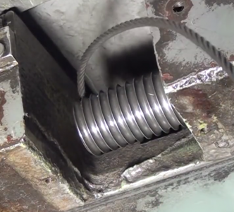
Screen Shot 2020-12-11 at 9.44.16 PM.png
My lathe can cut thread pitches from 4 TPI and up. If I grind a form tool to match the diameter of the cable I can cut the right shape groove. The part that stumps me is what pitch to cut.
I need someone to check my thinking...
A 3/16" cable is .1875" in diameter
4 TPI is going to cut grooves .25" apart.
5 TPI is going to cut grooves .20" apart
5.5 TPI is going to cut grooves .182" apart

So I think my choice is either 5 TPI which will leave a small flat between grooves or 5.5 TPI which won't leave a flat crest.
 
Last edited:
Depends on if you go full radius deep Dave . Either way , you're going to run into major chatter . I would suggest you start with a v thread cutter , the step up to an acme cutter , then go with your 3/16ths ball cutter . Get most of the meat outta there will reduce that chatter .

I made quite a few cable hubs for the Navy ships over the years , on a much larger scale . At first we turned them and fought the job quite a lot . We switched operations over to the 4rth axis on a large VMC and used a ball mill accordingly . This also saved another set-up because they had to go on the mill anyway after the scroll was machined .
 
I'm Planning on doing this to my Boyar Schultz 6x12 soon.... I can't wait to see what you come up with......
 
Depends on if you go full radius deep Dave . Either way , you're going to run into major chatter . I would suggest you start with a v thread cutter , the step up to an acme cutter , then go with your 3/16ths ball cutter . Get most of the meat outta there will reduce that chatter .

I made quite a few cable hubs for the Navy ships over the years , on a much larger scale . At first we turned them and fought the job quite a lot . We switched operations over to the 4rth axis on a large VMC and used a ball mill accordingly . This also saved another set-up because they had to go on the mill anyway after the scroll was machined .
Thanks Dave, that's good advice and well taken.
So if I don't go full radius deep then 5.5 TPI will probably work.
Unfortunately I don't have a VMC... and I don't think my rotary table is going to do the trick :)
 
and I don't think my rotary table is going to do the trick
Well ....................actually :grin:
I can remember way back when some kind of contraption they used that tied rotational movement in with linear movement on our Bridgeports . That was eons ago and they had some pretty darn bright machinists back then . I can't remember what I ate for breakfast this morning . :headache:
 
I know this is a crude solution, but bottom line is that you don't want "internal" gaps between wraps on the drum. I am basing my thoughts on the bridge cranes(30-310 tons), which would be a "little" heavier drums than what you are doing.

What I am thinking is to use stepped gears in the threading chain to alter the feed rate. I can't tell you what gears to use for several reasons. Not the least of which is I don't know your machine. I would start at 5 TPI and try gears until you get the desired feed rate.

Cutting threads that course will run the carriage fast. So run the nachine slow on a test piece of PVC or so until you find the right combination. Calculating it with math would probably help, but I'm slow tonight. I have used such a system to run "almost" metric threads on an old Atlas. Crude, but simple.

.
 
Well ....................actually :grin:
I can remember way back when some kind of contraption they used that tied rotational movement in with linear movement on our Bridgeports . That was eons ago and they had some pretty darn bright machinists back then . I can't remember what I ate for breakfast this morning . :headache:
I was imagining something that would advance the mill table at the required feed rate and turning the rotary table... No way could it be done manually by this human!
 
I know this is a crude solution, but bottom line is that you don't want "internal" gaps between wraps on the drum. I am basing my thoughts on the bridge cranes(30-310 tons), which would be a "little" heavier drums than what you are doing.

What I am thinking is to use stepped gears in the threading chain to alter the feed rate. I can't tell you what gears to use for several reasons. Not the least of which is I don't know your machine. I would start at 5 TPI and try gears until you get the desired feed rate.

Cutting threads that course will run the carriage fast. So run the machine slow on a test piece of PVC or so until you find the right combination. Calculating it with math would probably help, but I'm slow tonight. I have used such a system to run "almost" metric threads on an old Atlas. Crude, but simple.
What are stepped gears Bill?
Trying it in PVC is an excellent idea....
 
There are several(usually) gears between the spindle and the lead screw. As long as they run in the same plane, they are only idlers. The only control they offer is changing direction based on an even/odd number. A stepped gear is where two gears are keyed together, say a 60 and a 40. Driving the 60 into the 40 would reduce the output by a small precentage. My mind says 33%, but, like I said, I'm slow tonight. Basically, the same as a drill press, where the smaller the driveing(power) pulley and larger the driven(load) pulley, the slower the spindle runs.
.
 
Back
Top