LMS Mini Lathe Feed Rate - Vary Gears?

@MaverickNH

I was thinking about your desire to have a slower feed rate and the suggestion that you get a 127T gear. You could get two of these 3D printed, then assuming that they will fit, replace the 80/20/80/20 arrangement with 127/20/127/20 and I think this will get you to a TPI value of
645.16 or inverting this a feed rate of 0.00155 inch/turn. The nice thing about this would be that just using one of the 127 gears could also be used at the center position to improve your metric threads.

Just a passing thought. I have a "Prusa i3_MK3S" 3D printer. If you can make a 3D printer CAD STL file for it I would print them for you. I would like to see how well this would work anyway. Prusa even supplies a slicer software to convert from the CAD STL file to the Gcode file. https://www.prusa3d.com/page/prusaslicer_424/

I even think that FreeCAD software will generate 3D gears pretty much automatically from the gear tooth size and number of teeth or diameter info.

Dave
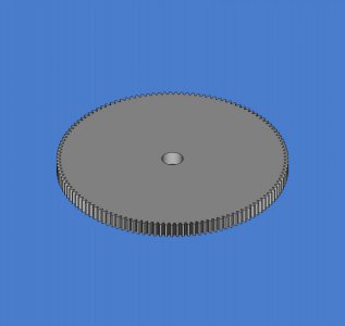
What's the bore and key way? I just did an 8mm thick 127T M1 gear with a 12mm bore in FreeCAD. Took about 2-1/2 minutes, only because I messed up the order of operations. Very easy, once you know the basics of FreeCAD. Likely the same with other CAD packages.
127TM1gear.jpg
Key way is 3mm, bore is 12mm, 8mm thick. New pic with key way.

127TM1gear3mmkey.jpg
What clearance should I give? I made the key 3.1mm wide and the bore 12.1mm since inside dimensions tend to shrink when printing. Is that ok?
 

Attachments

  • gear127TM13mmkey-Body.stl
    1.6 MB · Views: 0
Last edited:
What's the bore and key way? I just did an 8mm thick 127T M1 gear with a 12mm bore in FreeCAD. Took about 2-1/2 minutes, only because I messed up the order of operations. Very easy, once you know the basics of FreeCAD. Likely the same with other CAD packages.
View attachment 467153
Key way is 3mm, bore is 12mm, 8mm thick. New pic with key way.
View attachment 467156
What clearance should I give? I made the key 3.1mm wide and the bore 12.1mm since inside dimensions tend to shrink when printing. Is that ok?
I don't add clearance. I haven't for any of the gears I've printed, and haven't had a problem. I would print it out 12mm and tap it on. It has to be pounded on then I would run a 12mm drill through it (by hand if possible).
 
@WobblyHand , @MaverickNH

Thanks for making the STL file. I would have made it, but my copy of FreeCAD stopped working and I have not been motivated to start over. Nevertheless, I do need STL files for a 120 and 127 for my old SB10-K and had thought of making them. Just never got a round to it. There is a guy on ebay who sells this plastic set for various lathes.

Second thoughts. I am willing to make a gear. However, I realize that I really do not understand the mechanics of the LMS4200 gear changing system and how much room there is for large gears. My TPI finding program does not take physical spacing into account. Transfer gears (Imperial to Metric) are usually 127 paired with 120 on a single center axle on larger lathes, like my PM1440GT. Then the end gears can be change to various values to get different metric threads. But is there room on this small lathe. Other smaller lathes sometimes use 91/86 pairs to make metric threads (which is not quite as accurate but still works). But making metric threads was hot the initial issue. So if there is not room on the LMS4200 for pairs of larger gears then we are spinning our wheels. Others had suggested gears smaller than the 20T to satisfy @MaverickNH desire for a lower feed rate.

@MaverickNH has not chime in lately. Maybe we should hear what he wants to do?

Dave
 
Last edited:
@homebrewed

Yes, I too found 116 gear combinations for 16TPI. However, there were more as my program only counts once for the condition where the gears at A=D AND B=C. Since I consider each axle's possible gear to be any of the 11 available there would be 11 events where A=D and for each of these there would be 11 events where B=C. For example, A=D=50 and B=C=30 (or A=D=80 and B=C=20.... etc etc) gives a total ratio of 1, but the lead screw has 16 TPI so the over all TPI is 16. That would meant that there would be 11x11 - 1 = 120 more possible event s (one was already counted in the 116) .

Of the 116 gears yielding 16TPI that were found, there are a large number of the ones in the 116 set where A=B AND C=D, but A is not equal to D. This occurs simply because the center two positions turn at the same rate (1 axle). So these are a simple case of redundant situations and these need to be noted as a form of duplicated gears. I must have just missed this situation in my code. I will have to check in to this some time.

My program had found a total of 12,321 while eliminating some duplicates. This is about 1/2 of the number you came up, 24,402, so I suspect that yours was counting duplicates or something or you used more gears than 11?

Is my thinking correct, if no duplicates are eliminated it would mean that there were 11*11*11*11 possible combinations, which is only 14,641 possibilities. That is for a pair of axle each with a possibility of 11 gears. Then that pair can generate 121 combinations. Add another axle and for each of the 121 from the first two axles there are 11x new combinations where the 3rd axle takes on values. Likewise, for the 4 axle's 11. I am not for sure how you would have gotten up to 24,402 unless you had more gears available.

So I just ran my program with the "elimination of duplicates" feature turn off. As expected, I got 14641 cases.

I will message you later about the code. Anyway, I am not for sure when I will be able to spend a lot of time studying it. There are a lot of things on the plate and my working on HM has been a diversion! (-:
 
I don't add clearance. I haven't for any of the gears I've printed, and haven't had a problem. I would print it out 12mm and tap it on. It has to be pounded on then I would run a 12mm drill through it (by hand if possible).
Good to know. I find that holes, channels and threads run undersized. I always have to tap the threaded holes, or they are tight. The tap doesn't remove much, maybe a 0.1mm or less, kind of like fine fuzz. I can redo the gear if someone wants it. It would take about a minute or two, it's just a constraint value and then a export.
 
@B2 you can always try using an AppImage for FreeCAD. It's not a full system install, but it is more like a folder with everything that is needed. I have used them to see if my issue is a version problem or not.
 
@WobblyHand , @MaverickNH

Thanks for making the STL file. I would have made it, but my copy of FreeCAD stopped working and I have not been motivated to start over. Nevertheless, I do need STL files for a 120 and 127 for my old SB10-K and had thought of making them. Just never got a round to it. There is a guy on ebay who sells this plastic set for various lathes.

Second thoughts. I am willing to make a gear. However, I realize that I really do not understand the mechanics of the LMS4200 gear changing system and how much room there is for large gears. My TPI finding program does not take physical spacing into account. Transfer gears (Imperial to Metric) are usually 127 paired with 120 on a single center axle on larger lathes, like my PM1440GT. Then the end gears can be change to various values to get different metric threads. But is there room on this small lathe. Other smaller lathes sometimes use 91/86 pairs to make metric threads (which is not quite as accurate but still works). But making metric threads was hot the initial issue. So if there is not room on the LMS4200 for pairs of larger gears then we are spinning our wheels. Others had suggested gears smaller than the 20T to satisfy @MaverickNH desire for a lower feed rate.

@MaverickNH has not chime in lately. Maybe we should hear what he wants to do?

Dave
Sorry to have gone silent!

I've pulled my 7x12 apart to install a 7x16 bed and DRO kit, so won't know if >80-tooth gears will fit, cover off or on, until later next week. I have access to a nice 3D printer but am not up on CAD yet - I learned drafting on velum, HB lead holders and a Vemco drafting machine in the early 70s :)
The set that LMS sells for reducing the feed rate is an 80T/15T combo plus a 90T (80T/15T is the B/C set, which drives the 90T D gear); I'm assuming that the 90T fits without modification of the cover as that has been mentioned on other forums.
 
@WobblyHand , @MaverickNH

Transfer gears (Imperial to Metric) are usually 127 paired with 120 on a single center axle on larger lathes, like my PM1440GT. Then the end gears can be change to various values to get different metric threads. But is there room on this small lathe. Other smaller lathes sometimes use 91/86 pairs to make metric threads (which is not quite as accurate but still works). But making metric threads was hot the initial issue.

Dave
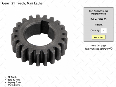
LMS sells a 21T gear that is used for some metric threads on inch 7x lathes:

Screenshot 2023-11-18 at 1.36.21 PM.png
 
The set that LMS sells for reducing the feed rate is an 80T/15T combo plus a 90T (80T/15T is the B/C set, which drives the 90T D gear); I'm assuming that the 90T fits without modification of the cover as that has been mentioned on other forums.

Well, dang! I missed that in my search of LMS but I think these will work nicely at 0.0026"/rev. Of course, I just placed an LMS order this week, so I'll have to place another!
 
Back
Top