LMS Mini Lathe Feed Rate - Vary Gears?

MaverickNH

H-M Supporter - Gold Member
H-M Supporter Gold Member
Joined
Nov 6, 2012
Messages
128
My LMS 4200 7x12 mini lathe comes with ACBD 80/20 gears for autofeed at 0.004”/rev. That’s fast enough, but can I slow it down to 0.002”/rev with different gears? I don’t see any mention of the ability to change autofeed rates in the manual beyond the threading range of 12-52 TPI (if I calculate correctly, that 0.083-0.019“/rev).

If not, is it an alternative to use a 2x larger radius cutting tool and take shallower cuts for finishing passes?

BRET
 
I don't know if you are familiar with Varmint Al, but he had done a wonderful job upgrading is HF mini lathe. One of his modifications was to add a small gear motor to the tail stock end of the lead screw on his lathe. While his motor was a fixed speed, by varying rpm he could effectively change feed rate. This modification required him to remove the gear on the head stock side of the lead screw when not in use and conversely disengage the little motor on the tail stock side when not in use. I did the same modification many years back to a micro-mark 7x14 for a customer and it worked wonderfully. I changed his parts list up a bit, using a bi-directional motor for added convenience. Here is a link to his page if you are not familiar with his work. Its worth reading if you own one of these little lathes.


edit: I just went back and re read Al's note on adding the motor. He used a 2.5rpm motor. I don't remember what motor I installed, but I am thinking that it was closer to 30 or 45 rpm. Again, feed rate becomes unlimited on these machines so the higher the rpm on the spindle, the finer the feed rate. I suppose you could use a variable speed motor as well at risk of loosing the super accuracy of these little synchronous motors.
 
Last edited:
Fine feed gears If you have a 3d printer you can print them yourself. These are module 1 gears. I believe there's enough info on the LMS page to design them yourself. I have modeled gears in FreeCAD. Assuming you know the CAD program, the modeling of the gears is a simple and fast process. I did buy this gear set when they first came out. They do reduce the feed rate by 1/2. A stock mini-lathe has no way to adjust the feed rate, it is fixed. So you need a motor like Varmint Al did, or special gears, or an electronic lead screw.
 
My LMS 4200 7x12 mini lathe comes with ACBD 80/20 gears for autofeed at 0.004”/rev. That’s fast enough, but can I slow it down to 0.002”/rev with different gears?
You maybe able to swap the gears around in an unconventional manor to obtain the feed rate. Unconventional simply means putting the gears in a configuration not described in the manual. Lathe manuals usually only provide a very few of the possible threading or feed rates that are possible.

I have posted an Excel spread sheet workbook that can be configured for almost any lathe gearing and it will then by using pull down menus to describe the gears at the various locations the feeds and TPIs appear in other cells of the spread sheet. I did this first for my PM1440GT, but later I added other sheets for other lathes, but simply copying the sheet and then changing the gears. We can probably do this for your lathe if you can provide a manual and some other descriptions from the lathe. Do you have a manual? If so post it. The really powerful part of the workbook is that I wanted to learn to write Excel macros so I did. There are several very useful macros that run the lathe sheet of your choice and then generated a list of ALL Possible gear position results. Other macros allow you to search this sheet for the exact value you want or for close approximations to the value. There are other macros for sorting the lists etc.. There is a sheet in the workbook with extensive Readme notes.

You can get the workbook at the link below or directly download the work book at the following HM URL . https://www.hobby-machinist.com/attachments/tpi_manylathesrev1-nb06_2023-zipped-zip.465427/

It is zipped because HM does not allow workbooks containing macros to be posted. Zipping the file hides this from the HM and allows it to be posted. Since I wrote the macros I know there is nothing harmful about them. In fact if you keep your Excel program set up so that it asks you before you enable macros you can look at the text file of them and see they are safe to run.

If you post the manual, a list of the gears, possibly some photos of the gear locations... that you have and which axles they will fit on .... I can take a look at generating the excel sheet for your lathe... or you can do it and I can answer questions. My guess is that your lathe does not have a gear box, only external gears? In this is the case, it is quite easy to set up the spread sheet. It is probably similar to the sheet I created for the PM1130V lathe. However, the number of gears listed in this sheet needs to be reduce as it is way to large to run the macros on. Doing so will take way too long.

Hi Folks,
Comments regarding experiences, additions, improvements made etc. about this project/Workbook would be appreciated.

Nov. 6 2023 Excel workbook file name: TPI_ManyLathesRev1 NB06_0054.xlsm

Edit: Corrected lathe sheet G4003G and so changed the file and its name to: TPI_ManyLathesRev1 NB06_2023
I got more info about the gears available in the the G4003G

The fundamental worksheet format and Macros have not changed, but
I added a couple of lathe sheets to the TPI generating Excel workbook. So I thought I would just post the current workbook.
It now has lathe sheets for the follow

Dave L.
 
If you're looking for a better finish, you might want to try a vertical shear bit. I used one on a mini lathe and was duly impressed at the finish on 6061 aluminum and 12L14 steel. I don't recall trying it on anything else. Only works for shallow cut finishing passes, ~.003" or so, as I recall.
Here's how to grind one: https://gadgetbuilder.com/VerticalShearBit.html

Tom
 
You maybe able to swap the gears around in an unconventional manor to obtain the feed rate. Unconventional simply means putting the gears in a configuration not described in the manual. Lathe manuals usually only provide a very few of the possible threading or feed rates that are possible.

I have posted an Excel spread sheet workbook that can be configured for almost any lathe gearing and it will then by using pull down menus to describe the gears at the various locations the feeds and TPIs appear in other cells of the spread sheet. I did this first for my PM1440GT, but later I added other sheets for other lathes, but simply copying the sheet and then changing the gears. We can probably do this for your lathe if you can provide a manual and some other descriptions from the lathe. Do you have a manual? If so post it. The really powerful part of the workbook is that I wanted to learn to write Excel macros so I did. There are several very useful macros that run the lathe sheet of your choice and then generated a list of ALL Possible gear position results. Other macros allow you to search this sheet for the exact value you want or for close approximations to the value. There are other macros for sorting the lists etc.. There is a sheet in the workbook with extensive Readme notes.

You can get the workbook at the link below or directly download the work book at the following HM URL . https://www.hobby-machinist.com/attachments/tpi_manylathesrev1-nb06_2023-zipped-zip.465427/

It is zipped because HM does not allow workbooks containing macros to be posted. Zipping the file hides this from the HM and allows it to be posted. Since I wrote the macros I know there is nothing harmful about them. In fact if you keep your Excel program set up so that it asks you before you enable macros you can look at the text file of them and see they are safe to run.

If you post the manual, a list of the gears, possibly some photos of the gear locations... that you have and which axles they will fit on .... I can take a look at generating the excel sheet for your lathe... or you can do it and I can answer questions. My guess is that your lathe does not have a gear box, only external gears? In this is the case, it is quite easy to set up the spread sheet. It is probably similar to the sheet I created for the PM1130V lathe. However, the number of gears listed in this sheet needs to be reduce as it is way to large to run the macros on. Doing so will take way too long.


Dave L.
The finest "threads" you can cut with the stock change gear set is 256 TPI, which produces the .0039" fine feed. You have to use both 20 and 80-tooth gears for that. The gears produce a 4*4 = 16:1 relationship between the spindle and lead screw, which is 16TPI. 16*16 = 256, so end of story, you don't get any better than that.

To get a finer feed you will have to either print some additional gears or take the Varmint Al approach. In the former case, you may have to remove the gear cover to accommodate the larger-sized gears.

There also is a fine-scheme approach that uses a different gear "banjo" that you have to make. Information on the fine-feed banjo can be found on https://groups.io/g/7x12MiniLathe/files/Richards folder, but you may have to become a member to access the file. It is claimed to produce about a factor-of-4 improvement over the standard banjo. I think that assumes using nothing but the standard gear set so it should be possible to achieve an even greater improvement if you use printed gears. However, if you take that route the banjo probably will have to be redesigned to accommodate the larger-diameter gears.

These days, given the ubiquity of 3D printers I don't think it makes much sense to go with the Varmint Al scheme unless for some reason you need a really super-fine feed.

In lieu of those approaches, a vertical shear bit works pretty good. Or simply using a larger-radius cutter for a finishing pass.

If you do go with larger gears I highly recommend printing a 127-tooth gear. That also will allow you to cut very accurate metric threads on an imperial machine. Just that gear alone will get you to a .0025"/revolution feed rate, assuming you install a set of 20, 80, 20 & 127 tooth gears.

None of these schemes provide an auto-stop function -- but the Varmint Al slow feed approach could easily support that. Something to consider.
 
The finest "threads" you can cut with the stock change gear set is 256 TPI, which produces the .0039" fine feed. You have to use both 20 and 80-tooth gears for that. The gears produce a 4*4 = 16:1 relationship between the spindle and lead screw, which is 16TPI. 16*16 = 256, so end of story, you don't get any better than that.

I was not trying to interfere, just trying to help out. I went to all of the trouble to built that workbook and though it might be helpful.
I do not know this lathe nor its gearing or gear arrangements. That is why I requested the manual/pictures/etc. I found a very poor quality photo of the front of the machine and could not see a gear box, but no manual. So I assumed that all gearing changes occurred at the external gears. But I found no picture of these external gears nor their arrangement. But I assumed there would be at least a banjo to form a center axis. If not then all one can make are the ratios of the two gears sizes, where the gears are attached essentially to the spindle and to the lead screw directly. I would agree with you that the simplest thing is to use a 3D printer to make other gears, but a 20T gear is pretty small to maybe cannot be made any smaller? It also sounds like an 80T is pretty large on this lathe so is there physically room for a larger gear than 80T. He ask if he could halve the rate so that would mean that the gear would need to be twice as large 160T. Since the diameter is proportional to circumference and the tooth size is a constant that would mean that the 160T gear would be twice the diameter of the 80T gear. You said remove the cover, but is even that going to be sufficient? I would still be interested in seeing a manual and picture of how the gears physically mount to the machine.

Having said all of that, if there are some gear arrangements which have not been listed in the manual the spread sheet could quickly generate the complete list. This might be handy for non-standard threads. It would be trivial to set up the spread sheet by just setting the transpose gears to a ratio of 1. But one still needs to know what gears are available.

Dave L.
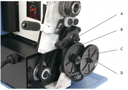
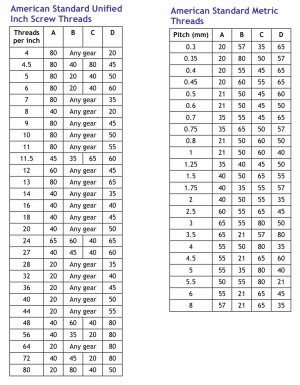
Here’s that manual and the pic/chart for gearing https://littlemachineshop.com/products/product_view.php?ProductID=4924

The default 0.004”/rev is ACBD 80/20 gearing.

IMG_2553.jpegIMG_2554.jpeg
 
The lead screw on my now departed china 8", spun so fast that I couldn't slow it down enough to make the auto feed useful when doing simple turning cuts. Maybe I should have explored different gears, but the metal gears I had were really noise and there was a lot of gear wobble, and larger gears wasn't going to help out that situation. They wouldn't have fit under the back cover either.

Anyway, I bought a speed control, a Dell laptop power supply, and a drive motor, which looks a little like a car wiper motor. My plan was to drive the lead screw using this setup, and disconnect the system from the main drive system, unless the day came to make threads. Best laid plans...which I never got around to implementing. The parts are laying in a box, waiting for me to dispose of. Someday...
 
Here’s that manual and the pic/chart for gearing https://littlemachineshop.com/products/product_view.php?ProductID=4924

The default 0.004”/rev is ACBD 80/20 gearing.

View attachment 466845View attachment 466846
In the deep reaches of my mind I seem to recall that someone was selling a pair of 14 tooth change gears that replaced the 20 tooth gears and would theoretically yield 0.002"/revolution [(14÷80 x 14÷80) ÷ 16 {lead screw pitch} = 0.0019; as a check, (20÷80 x 20÷80) ÷ 16 = 0.0039]. I'll keep searching my various references.

You have me intrigued, so I'm also seeing what I can find on eBay from China, just to try it.
 
Back
Top