HELP? G4003G

Wish it would have worked for you, I will keep your e mail just in case something was to come up. I,ll send you an e mail so you get my info as well we live close enough to each other to at least help out if needed. Thanks
 
I'm not sure the 4000 is the same but It would be easy to see if it would fit, it's a flat gear, with no hub or collar. The bore is .630 (16mm) with a .200" (5mm) key and 10mm thick
Email is my username name at Gmail.com I'm south of Hartford about 4 miles

I found a manual for a 4000, the part looks the same, I would have to see if the pitch is the same and the bore and such match

Do you own a 3d printer, or have a friend who does? I can model a gear stl file for you in about half a minute.

A 3d printed gear won't last forever and isn't the strongest option, but it's advantage is that you can print as many as you need. If you learn CAD, you can print them in any possible tooth count for pennies in material, and consider them disposable.

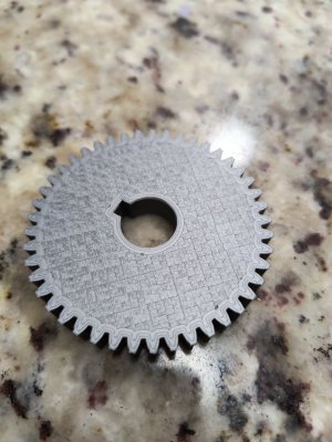
Here is a .stl file for a 45t module 1.5, 20* PA, gear. I gave it a 16.25mm bore with a 5.2mm keyway, to allow some sliding clearance, and allow for the tendency of most off the shelf, not-fine-tuned 3d printers to print holes a little undersize.

I modeled one in Alibre Design and am printing it, just to see how it turns out. If you don't have access to a 3d printer, I can mail this gear to you if you need.

the STL file is attached.


Edited to add: For anyone who doesn't have access to CAD or is otherwise unable to model their own gear design, there are online gear generators that will generate a .stl for you. Just input the necessary information. Just make sure to account for sliding clearance in the bore and keyway size. I think (could be wrong) that the G4003 and G4003G both use a 1.5 module, 20*PA. In the generator link below, gear length is the gears thickness.

IMG_20231106_063956408.jpg
 

Attachments

  • G4003G 45T Gear.stl
    742.9 KB · Views: 3
Last edited:
Never assume! this thread requires the 45t gear which was not in the sealed bag

What external gears do you have? Are all of the gear axles the same size so that any gear can fit on any axle?

I do not know your lathe, but quickly looked at the manual. It does not seem to say which external gears you have. If you have a few you could use the Excel workbook I developed and posted on HM to see you you might have a combination that will generate the 3TPI thread. The workbook has has a few lathe models built into it already, but is pretty easy to modify to fit almost any possible lathe gear geometry. The point is that the manufactures do not list all of the possible TPI values that can be achieved with all the possible external and internal gear arrangements.

Here is the link to the Excel workbook. I suggest that you download the zipped version which has built in macros. One of the macros will cause the spread sheet for a the lathe tab that you select to generate ALL of the possible TPI values where you have listed the External gears you have on hand (or might by). You can sort or search this list of ALL possible TPI values via the other macros and see if there is a 3TPI gear arrangement.
Re: Improved Version: TPI, Feeds, X-Feeds: Generalized Lathe TPI Excel file: "TPI_ManyLathesRev1 N502_1630"

Your lathe has a Norton gear box with 8x5 possible possible internal gear ratios. One of the lathe templates that is in the workbook is the PM1340GT (which has the same gearing as the PM1236T). It has a similar Norton gear box so might be a good starting point for you. I do not know if the internal gears are the same as your G4003 so changes maybe be necessary to get your internal gear ratios correct. I suspect this to be the case as I have found other references that says your change gear for metric conversions are 91/86 rather than the 127/120 that the PM1340GT uses.

Anyway, I am willing to help you to figure this out.

Dave L.
 
@TakeDeadAim

Ok, I did a little spread sheet testing and it looks like the G4003 uses the same gear ratios as the PM1340GT. So the spread sheet should work for you. However, the external gears are a bit different, as is the 91/86 exchange gear. I will run my program and see what come out. I found a different manual for the G4003 and is has the supplied external gears listed: 26, 27, 35, 36, 40, 40, 45, 50, 60, 86/91

I will run the spread sheet to later to generate all possible TPI values, but for now I think that if you put the 60T at the bottom (Gear boxs input) and the 40T at the top (spindle position) and you select the Norton configuration to be 2A you will find that you get 3.00TPI. Likewise, there will be other arrangements that my yield the 3TPI or close approximations. (By the way, the spread sheet DOES also say that if you use the 60T at the top, the 45T at the bottom, and the gear box at 1A you will get 3TPI.) So maybe you do not need at 45T at all!

Please check this out before cutting!
 
@TakeDeadAim

Looks like there are several ways to make the exact 3TPI value. Again, I do not have your lathe so cannot check to see if I have made any errors in setting the spread sheet up. But I think it is correct.

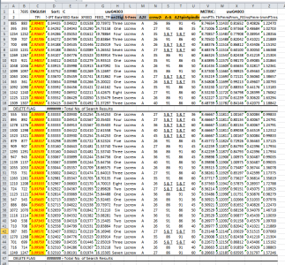
Here is a table showing all of the ways that you can achieve 3TPI and approximations to it. If you wanted to accept a more threading error then their would be more possible approximations available. Note the TPI value is in yellow at column C. Column A and B are scrambled line numbers and are unimportant to the table. To the right of each TPI value, starting at column H are the gear box settings followed by the external gear arrangements. Note that at column N corresponds to the bottom gear and column S corresponds to the top gear(spindle). A number of these require that you use the exchange gear with either the 91T next to the bottom gear or the 89T next to the bottom gear, i.e. you have to flip it over. I did not check the feed and x-feed numbers to see if they were correct for your lathe (the x-feed tables on many lathes have errors in them.) , but these values are at columns D-F. Column G would be the TPI value if you were cutting a thread using the feed bar (this may not be possible with some lathes) In concept, some lathes can also thread using the feed position, but here column L indicates that the threading lever position is applied, not the feed position. When two columns say things like S&T it means that any gear maybe be placed at these two columns, S and T. In this case this is the exchange axle positions, inside and out. I will try to post the full spread sheet tomorrow (It always takes me a bit to figure out how to zip a file so that HM will allow be to post the workbook with macros.) By the way, without changing the exchange gear tooth values other than flipping it over, Cell B1 indicates that there are a total of 7695 possible TPI values for this lathe using the standard supplied external gears. However, in some lathes the exchange gears are physically similar to the other gears and one can then change one of these, say substitute the 50T for the 89T etc. i.e. make it a 50/91 exchange gear. This would make the 7695 number MUCH larger.

Lastly, most of us hobby guys cannot measure the difference between an exact thread and a thread which is made with a couple of percentage points off, say a 3.06TPI or a 2.94TPI. We can only determine this is in error by making a very long and tight thread and measuring carefully. So with that in minded you have a lot of options.

1699252537348.png


PS. If you are really picky and want to be more accurate with your metric threads you might consider changing to the 127/120=1.0583333... exchange gears rather than the 91/89=1.0224719... Which is a only few percentage points different but represents the mechanical conversion between mm and inches. After all 127 x 2 = 254. 25.4mm=1 inch

Dave L.
 
The workbook was posted at:

Nov. 6 2023 Excel workbook file name: TPI_ManyLathesRev1 NB06_0054.xlsm

The fundamental worksheet format and Macros have not changed, but
I added a couple of lathe sheets to the TPI generating Excel workbook. So I thought I would just post the current workbook.
It now has lathe sheets for the following lathes, but many other lathe models are similar or the same...just by different names.

NB06: Currently Available, LatheModel TPI sheets:
PM1440GT
PM1440HD - ( @Larry$ @verbotenwhisky )
PM1340GT_PM1236T
PM1236-1236M
JET-BD1340
Atlas618
MMLB-Norton - ((MetalMax) @Provincial )
MM1340LB-Lever - (MetalMax)
PM1228VF-LB - ( @LROYSON , @Aurelius )
G4003G=G4003 - (waiting feedback from @TakeDeadAim)
PM1130V - (TBD: @JPMachine to review. Remove some gears before running the GenAllTPI_14V2 macro)

Dave L.
 
What external gears do you have? Are all of the gear axles the same size so that any gear can fit on any axle?

I do not know your lathe, but quickly looked at the manual. It does not seem to say which external gears you have. If you have a few you could use the Excel workbook I developed and posted on HM to see you you might have a combination that will generate the 3TPI thread. The workbook has has a few lathe models built into it already, but is pretty easy to modify to fit almost any possible lathe gear geometry. The point is that the manufactures do not list all of the possible TPI values that can be achieved with all the possible external and internal gear arrangements.

Here is the link to the Excel workbook. I suggest that you download the zipped version which has built in macros. One of the macros will cause the spread sheet for a the lathe tab that you select to generate ALL of the possible TPI values where you have listed the External gears you have on hand (or might by). You can sort or search this list of ALL possible TPI values via the other macros and see if there is a 3TPI gear arrangement.


Your lathe has a Norton gear box with 8x5 possible possible internal gear ratios. One of the lathe templates that is in the workbook is the PM1340GT (which has the same gearing as the PM1236T). It has a similar Norton gear box so might be a good starting point for you. I do not know if the internal gears are the same as your G4003 so changes maybe be necessary to get your internal gear ratios correct. I suspect this to be the case as I have found other references that says your change gear for metric conversions are 91/86 rather than the 127/120 that the PM1340GT uses.

Anyway, I am willing to help you to figure this out.

Dave L.
I ran it through a program to see if any combination of what I have would get me a ratio that will produce what I need. The actual change gears all run on the same shaft then there is the 91/86 switch gear. The shaft driving the Norton type box has a different size shaft and takes a gear with a collar on it and different key. PM uses a different gear than my lathe and the job requires a precision fit. It seems the designer comes up with a combination that gets the common metric sizes but in reality it is designed to cut SAE type threads and requires the one combination to reach the metric threads
 
@TakeDeadAim

Ok, I did a little spread sheet testing and it looks like the G4003 uses the same gear ratios as the PM1340GT. So the spread sheet should work for you. However, the external gears are a bit different, as is the 91/86 exchange gear. I will run my program and see what come out. I found a different manual for the G4003 and is has the supplied external gears listed: 26, 27, 35, 36, 40, 40, 45, 50, 60, 86/91

I will run the spread sheet to later to generate all possible TPI values, but for now I think that if you put the 60T at the bottom (Gear boxs input) and the 40T at the top (spindle position) and you select the Norton configuration to be 2A you will find that you get 3.00TPI. Likewise, there will be other arrangements that my yield the 3TPI or close approximations. (By the way, the spread sheet DOES also say that if you use the 60T at the top, the 45T at the bottom, and the gear box at 1A you will get 3TPI.) So maybe you do not need at 45T at all!

Please check this out before cutting!
I have one each of; 26,27,35,40,50 that fit on the F (spindle) position. and a 40 and 60t that fit on the G (gearbox) position along with the 91/86 exchange gear. My lathe is a G4003G which has a different gearbox, the combo of 40 up top and 60 below in position 2A is finer than 3.0
 
@TakeDeadAim
Sorry to hear that the gears are different. If the axles are sufficiently different in diameter perhaps an insert adapter can be made.
Anyway, I just posted the workbook/spread sheet that does not take the different axle diameters into account. Maybe you will want to run it with the macro to suit your lathe. Just remove or add gears at the locations of the pull down menus, row 30, columns O to V. The cell entry Zzz is a necessary flag to stop the macros so if you remove gears values or add them type the flag at the end of the list.

If I understand correctly, you only have one gear that fits the axle gear box. Is that the 40T gear? If so this is a bummer. However, you can probably move other pairs of gears to the exchange gear position and get all kinds of values. There is just a concern about physical spacing. Also, the spread sheet does not know if you have extra copies of gears or not it just assumes that if you put the number in the column it is available with some arrangement of the other gears.

Good luck.

Dave L.
 
Do you own a 3d printer, or have a friend who does? I can model a gear stl file for you in about half a minute.

A 3d printed gear won't last forever and isn't the strongest option, but it's advantage is that you can print as many as you need. If you learn CAD, you can print them in any possible tooth count for pennies in material, and consider them disposable.

Here is a .stl file for a 45t module 1.5, 20* PA, gear. I gave it a 16.25mm bore with a 5.2mm keyway, to allow some sliding clearance, and allow for the tendency of most off the shelf, not-fine-tuned 3d printers to print holes a little undersize.

I modeled one in Alibre Design and am printing it, just to see how it turns out. If you don't have access to a 3d printer, I can mail this gear to you if you need.

the STL file is attached.


Edited to add: For anyone who doesn't have access to CAD or is otherwise unable to model their own gear design, there are online gear generators that will generate a .stl for you. Just input the necessary information. Just make sure to account for sliding clearance in the bore and keyway size. I think (could be wrong) that the G4003 and G4003G both use a 1.5 module, 20*PA. In the generator link below, gear length is the gears thickness.

View attachment 465361
I am seeing if a guy near me can print this, thanks
 
Back
Top