Heavy 10 5C drawbar

So threading was a disaster. 20 TPI, so any marking on the thread dial, right?

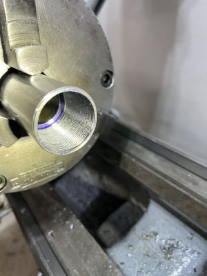
The scratch pass was good, matches the thread gage. A few more passes looked good, then all my Dykem blue disappeared after a whole bunch of passes.

I then noticed that the threads didn’t look very thread-like. Looked like something got cross-threaded.

Anyway, I have plenty of length. I parted it (which surprisingly went better than I expected), and started boring again.

Not sure what I did wrong on the threading. I’m using the compound to feed (~29.5 degrees), with a dial indicator on the tool post. I was disengaging the half nut, fed the cross slide in, slid the apron back, re-zeroed with the cross feed, advanced the thread tool with the compound and re-engaged the half nut at one of the lines on the thread dial.

When I try it again, I’ll err on the side of caution and pick one of the numbered lines and stick with that for subsequent passes.

Worse case scenario would be too much play somewhere on the lathe’s drivetrain, which would be bad…

Any advice? Thanks.
 
I would try making internal threads with some larger stock so it is easier to see what is going on. Also try several different thread pitches to see if you can find where the problem lies.

No insult intended, but if it were me, it would most likely be operator error. I find internal threads a bit challenging and doing some practice runs on scrap (even using PVC pipe) makes for better results on the final piece.
 
I checked the compound and the cross feed.

After advancing the compound, I found that my gage would climb back down. I thought maybe my gage setup was not rigid enough so I really cranked it down and felt the compound move. The compound has some significant play, about 2mm of wiggle forward and back. I’m guessing this is the problem or at least one of many. Still think my lack of experience contributed to it.
 
On any control you have to find out what the backlash in the mechanism is, then when you retract make sure you retract more than the backlash. That way when you go back the other direction, the backlash is completely canceled before you get to your next dial reading.

I have troubles sometimes finding a suitable place to mount my dial indicator so that it stays rigid throughout the whole operation. I need better indicators and mounts but there are ways to work around them for the time being.

Also, I found lots of good tutorial videos online. People like Blondihacks, ThisOldTony or Abom79 are good places to start. There are many others but these are the first ones on my go to list for setups and techniques when I get stuck on something.
 
My guess is that you're not working against the slop in your compound. A pic of your setup will help diagnose your issues. Where is the compound "wiggle" coming from - leadscrew backlash, or side to side movement?
 
My guess is that you're not working against the slop in your compound. A pic of your setup will help diagnose your issues. Where is the compound "wiggle" coming from - leadscrew backlash, or side to side movement?
A couple of things: I took the compound off and noticed that the compound rest nut was loose (the screw on the back side of the nut). I also tightened up the gib to help with the play. As a side note, since I’m new to operating a lathe, I didn’t have a feel of how tight to get the compound & crossfeed parts after the rebuild. Apparently, I had them too loose.

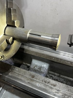
That did it. I finished the threading and all my collets fit nicely.

Everyone’s advice is appreciated.

93EC5E6D-E484-4AD4-ABCD-4E74B303EEA6.jpeg

3CBEAF10-9A5E-49C7-AA8B-8D8A4E157AD2.jpeg

Up next: That tapered piece that butts up against the back side of the spindle.
 
Are you using thrust bearings in your design?

Do you have plans on what you intend to build? If you do, post them here so that they can be viciously torn apart! (j/k)!
 
I used thrust bearings when I made a draw tube for my SB9. Makes things very smooth.
3a88e27e31793a650623cce2e2b6a139.jpg


Cutting oil is my blood.
 
I used thrust bearings when I made a draw tube for my SB9. Makes things very smooth.
This it does. Having thrust bearings can mean the difference between being able to grip your work in the collet and having your work slip in the collet. They are pretty much a necessity.
 
Are you using thrust bearings in your design?

Do you have plans on what you intend to build? If you do, post them here so that they can be viciously torn apart! (j/k)!
Not so much in written plans… it’s more like a mental outline.

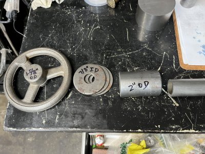
I took a pic to show the general ideal. What’s missing is a 1/16” OD bar stock that will go into the back of the draw tube which will be turned down to a 7/8”-9 tpi so it can mate with the handwheel I bought which is supposed to have a 1-5/8” hub (too small an OD for a 35x52mm thrust bearing). The handwheel will be bored for 7/8”-9 tpi to mate with the bar stock. The bar stock and drawbar will be drilled / tapped with set screws to secure it. Or, depending on the cost of material, I can get a 1-1/8” OD bar stock and thread it to both the draw tube and the handwheel.

The three washers in the pic show where the 35mm ID thrust bearing will be, sandwiched between washers under the handwheel. I’m waiting for the thrust bearing to arrive but I think I only need one washer under the handwheel.

3EA2495D-0CED-4704-AAD4-F04B36E59907.jpeg
 
Back
Top