Hello and thank you in advance for any help.
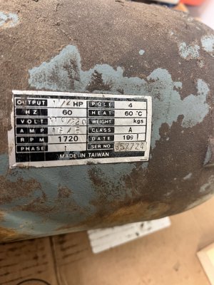
I bought this lathe Sunday, on said lathe is a 110/220 4 pole single phase 1.5hp motor that is original to the lathe.
Running on 220v single phase power.
As is, when the spindle lever is flipped up at the apron the motor starts and spins the chuck counter clock wise if facing the chuck away from the tool post. If I flip the lever down the motor bucked hummed and blew the motor capacitor.
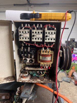
The three contractors operate what I think is correct, MS closes when the “power/arm” button is pressed, this has to been don’t to make anything work.
The one labeled ms1 closes when the carriage lever is switched to the up position.
This is the direction that blew the original capacitor.
MS2 closes when the lever is in the down position, this is the only way to get the motor/chuck to spin.
I’ve included some photos.
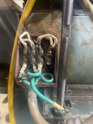
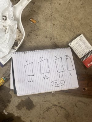
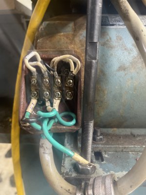
The motor wiring diagram shows 1,2,3,4,5,6 but the physical wires are 1,2,3,3,4,5,6
So I did label the 3 that was connect as 31 or 3prime. The lathe itself has 5 wires to the motor u1, v2, z1 and z2 was disconnected and taped.
As of now and as the way I received the lathe;
M=motor side
L=lathe power to motor
Lu1 to m1
Lv2 to m3prime
Lz1 to 5
236 are tied together but not connect to power.
I’m pretty proficient with a multimeter, but I don’t want to damage anything or make any bone head mistakes. Hopefully this is well written enough to get me going.
Thanks again,
Jeff Fort Wayne Indiana
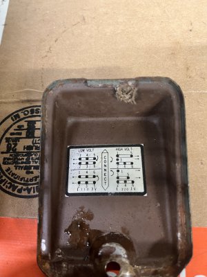
Edit*1 added incoming voltage and motor connection photo
I bought this lathe Sunday, on said lathe is a 110/220 4 pole single phase 1.5hp motor that is original to the lathe.
Running on 220v single phase power.
As is, when the spindle lever is flipped up at the apron the motor starts and spins the chuck counter clock wise if facing the chuck away from the tool post. If I flip the lever down the motor bucked hummed and blew the motor capacitor.
The three contractors operate what I think is correct, MS closes when the “power/arm” button is pressed, this has to been don’t to make anything work.
The one labeled ms1 closes when the carriage lever is switched to the up position.
This is the direction that blew the original capacitor.
MS2 closes when the lever is in the down position, this is the only way to get the motor/chuck to spin.
I’ve included some photos.
The motor wiring diagram shows 1,2,3,4,5,6 but the physical wires are 1,2,3,3,4,5,6
So I did label the 3 that was connect as 31 or 3prime. The lathe itself has 5 wires to the motor u1, v2, z1 and z2 was disconnected and taped.
As of now and as the way I received the lathe;
M=motor side
L=lathe power to motor
Lu1 to m1
Lv2 to m3prime
Lz1 to 5
236 are tied together but not connect to power.
I’m pretty proficient with a multimeter, but I don’t want to damage anything or make any bone head mistakes. Hopefully this is well written enough to get me going.
Thanks again,
Jeff Fort Wayne Indiana
Edit*1 added incoming voltage and motor connection photo
Attachments
Last edited: