Fixturing and toolpaths for noobs

Did you model the bolt heads to avoid collision? I guess as long as your retract heights are above you are probably OK.

I tend to model anything (sometimes roughly - rectangular blob as a clamp for example). Not really needed here as long as pay attention to the linkage moves.

This has been a good thread (I'm still trying to improve my CNC) - Just did a project and used 1/4" dowel pins to align a part that I had to flip over. Worked like a champ.
 
I very much appreciate the suggestions above and especially the step-by-step by @JimDawson.

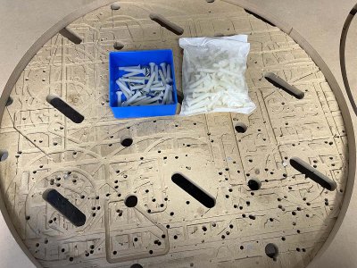
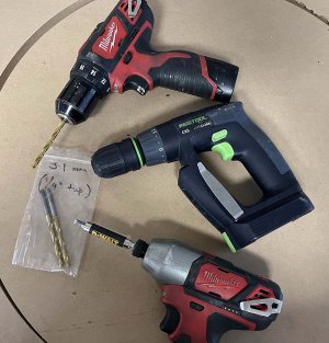
I find fixturing and the second operation (flipping over, releasing part from material, etc) to be the hardest part of milling. I didn't expect this. I have played for a few years with a CNC router, and usually cut plywood or MDF with occasional 1/8" alu sheet. Always cut through the whole thickness so it is more like 2D milling. I have a sacrificial MDF base with 20mm dogholes and slots, and my fixturing approach is straightforward: push the sheet against dogs and clamp it. Then for the part design 1/4" holes if possible or just hide a few in the design. Drill 5.1 mm holes, tap with 1/4"-20, then use 1-1/2" long nylon screws (McMaster 92929A230) to secure the part. This works very well for the lateral forces seen in routing even with 1/8" Alu. Sometimes with MDF jigs, simple designs, etc I just use pneumatic nails.

For proper 3D milling, I will have to rethink my entire approach. I have a LMS Alu fixture plate that will most likely be the main help. I am not confident MDF can withstand the lateral forces in real metal milling, but I see that that is being discussed by more experienced people, so will keep an open mind.

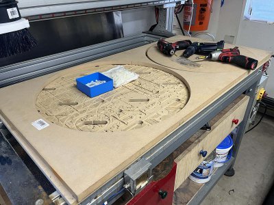
Here are a few shots of my router setup:

A sheet of MDF from which I cut a circle so my daughter can paint it and wife use is a serving plate. You can see a few nylon screws that were left in the sacrificial top.
IMG_0289.jpg

Fixturing sequence (5.1mm - tap - screw), although for this particular case I use pneumatic nails. The screws have slots so they shear off if overtorqued. They are long enough that when using thin material, I can reach below and unscrew by hand, or simply leave and forget.
IMG_0290.jpg

Big picture:
IMG_0291.jpg
 
I find fixturing and the second operation (flipping over, releasing part from material, etc) to be the hardest part of milling. I didn't expect this.
Where possible I prefer to do all of the work from one side and not flip the part over, and I'll go to great lengths to accomplish that. Including adding screw holes that are only used for the hold down. But sometimes it is unavoidable. If flipping the part is required, then dowel pins, or form fit fixturing is the answer.

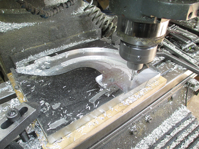
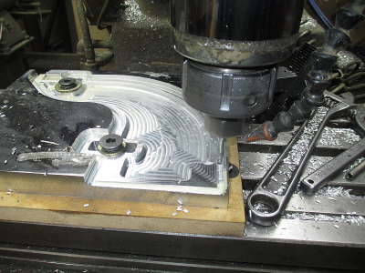
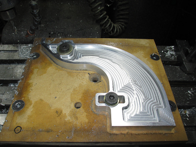
Here is a odd shaped part that I made for a project, required work on both sides. 1'' thick aluminum. Note the two drilled holes in line with the T slots, one towards the top, and the other towards the bottom. There are T nuts staged under those holes
1657504305635.png

Now I can use those as hold downs
1657504604571.png

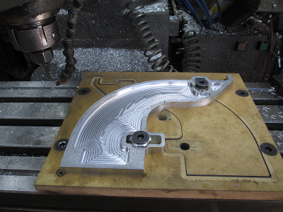
Once the part is completely profiled I need to turn it over and do the work on the other side.
1657504778893.png

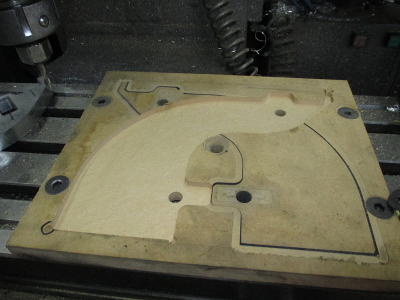
So now we do a mirror and machine a part shaped pocket, about 1/4'' deep, in the MDF. Note the holes to access the T slots again.
1657505079354.png

Because the pocket was machined to an exact fit, basically a press fit, I probably could have held it down with a couple of deck screws, which many times I use with MDF. All of the radial loads are taken by the pocket, you really only need to keep the part from pulling up. Machining the pocket and the part in one setup insures that everything lines up correctly, both use the same 0/0 setup.
1657505396449.png


I have played for a few years with a CNC router, and usually cut plywood or MDF with occasional 1/8" alu sheet. Always cut through the whole thickness so it is more like 2D milling. I have a sacrificial MDF base with 20mm dogholes and slots, and my fixturing approach is straightforward: push the sheet against dogs and clamp it. Then for the part design 1/4" holes if possible or just hide a few in the design. Drill 5.1 mm holes, tap with 1/4"-20, then use 1-1/2" long nylon screws (McMaster 92929A230) to secure the part. This works very well for the lateral forces seen in routing even with 1/8" Alu. Sometimes with MDF jigs, simple designs, etc I just use pneumatic nails.

For proper 3D milling, I will have to rethink my entire approach. I have a LMS Alu fixture plate that will most likely be the main help. I am not confident MDF can withstand the lateral forces in real metal milling, but I see that that is being discussed by more experienced people, so will keep an open mind.

I normally just use whatever scraps I have kicking around as fixture plates, be it aluminum or MDF.
 
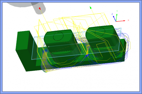
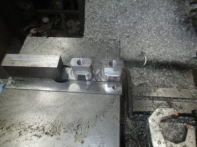
Another interesting work holding exercise. In this case two special T-nuts. This is one of the rare instances that leaving the part attached to the base material makes sense. I have only actually done this two other times. In one case it was another set of T-nuts, and the other ''U'' shaped part that did not lend itself to other holding techniques.


1657924733091.png


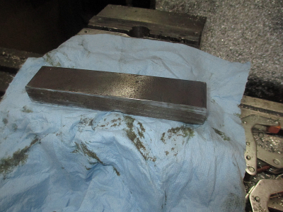
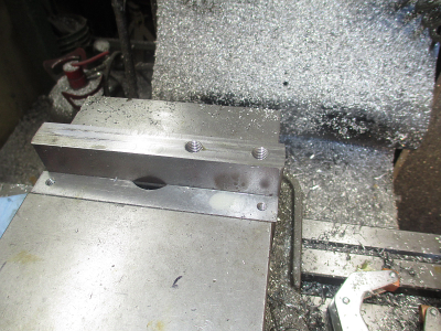
So start out with a 1 1/4 x 3/4 x 6 chunk off of the steel scrap excess inventory shelf. Not sure what it is, A36 or 4140? Some kind of hot rolled.

1657924792895.png

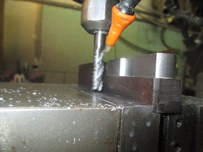
Face it off, with a 3/8 end mill, no face mill or flycutter required. Then cut a dovetail to match the dovetail in the vice jaws. WAIT! WHAT? Dovetail in the vice jaws? o_O

1657924926811.png

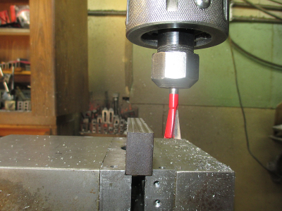
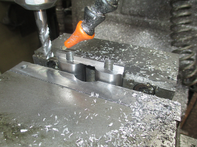
Yup, dovetail in the vice jaws. These are steel soft jaws. While I own a set of hard jaws, they sit on the shelf and gather dust, I don't use them. I make steel and aluminum soft jaws as needed, I have even made MDF jaws for special holding needs. I have been using this particular set of soft jaws for at least 4 years. Much more versatile than hard jaws, don't kill cutters when you run a tool into to them, as well as being machinable for fixturing as needed. Make soft jaws, remove your hard jaws, and store them on the shelf.

In this case the shallow dovetail adds an extra layer of security because the part is so tall relative what I'm hanging on to, and I'm taking a 0.500 depth of cut with a 3/8 endmill. Probably doesn't need it, but only takes a couple of minutes to add the dovetail. That part is not going to come out of the vise. I just used a 14° dovetail router bit.
1657924982274.png

Face off, drill & tap the the holes

1657925081842.png

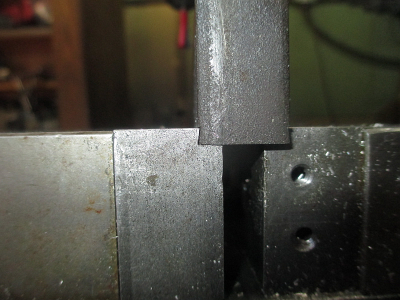
About 0.050'' clearance above the vise jaws at closest point.

1657925173505.png

And done with this side. Then over to the band saw to trim off the excess.

1657925376167.png

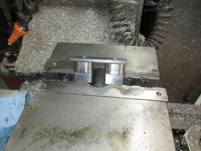
Flip over and put in the vise

1657925340108.png

Chew off the 0.181'' excess material. And done.
1657925504000.png
 
Last edited:
Another interesting work holding exercise. In this case two special T-nuts. This is one of the rare instances that leaving the part attached to the base material makes sense. I have only actually done this two other times. In one case it was another set of T-nuts, and the other ''U'' shaped part that did not lend itself to other holding techniques.[...]
So start out with a 1 1/4 x 3/4 x 6 chunk off of the steel scrap excess inventory shelf. Not sure what it is, A36 or 4140? Some kind of hot rolled.[...]
Face it off, with a 3/8 end mill, no face mill or flycutter required. Then cut a dovetail to match the dovetail in the vice jaws. WAIT! WHAT? Dovetail in the vice jaws? o_O[...]
Yup, dovetail in the vice jaws. These are steel soft jaws. While I own a set of hard jaws, they sit on the shelf and gather dust, I don't use them. I make steel and aluminum soft jaws as needed, I have even made MDF jaws for special holding needs. I have been using this particular set of soft jaws for at least 4 years. Much more versatile than hard jaws, don't kill cutters when you run a tool into to them, as well as being machinable for fixturing as needed. Make soft jaws, remove your hard jaws, and store them on the shelf.

In this case the shallow dovetail adds an extra layer of security because the part is so tall relative what I'm hanging on to, and I'm taking a 0.500 depth of cut with a 3/8 endmill. Probably doesn't need it, but only takes a couple of minutes to add the dovetail. That part is not going to come out of the vise. I just used a 14° dovetail router bit.
Face off, drill & tap the the holes [...]
About 0.050'' clearance above the vise jaws at closest point. [...]
And done with this side. Then over to the band saw to trim off the excess. [...]
Flip over and put in the vise [...]
Chew off the 0.181'' excess material. And done.
This step-by-step is very useful, thank you!

I have finished the project from the beginning of this thread.

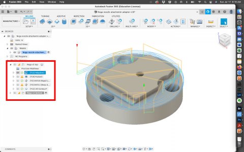
I still needed to flip it over. Starting with the blank, I shaped the top, then milled the countersinks, spot- and peck drilled, then milled out the outside contour. Having the TTS system and the sure makes life easy, and a tool touch-off greatly simplifies using one-off drill bits.


Screen Shot 2022-07-17 at 9.16.17 AM.jpg

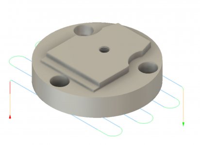
After flipping over, I faced the material to shave off the remainder, down to 5-10 thou. Because the bottom edge had a lip, I had chamfered it 20 thou. This last step required holding in the vice; I probed the middle hole (it is not center, so orientation matters) then chamfer. So it is complicated to design and has three steps. As a hobbyist AND BEGINNER it was acceptable, but I will surely pay attention to streamlining the process from now on.

Screen Shot 2022-07-17 at 9.16.52 AM.jpg


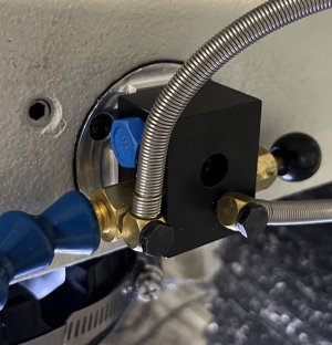
And here is the final product, assembled: a holder for a Noga mist nozzle to go intot hte recess from the quill lowering assenbly that I removed as a converted to CNC.


Noga nozzle attachemnt.jpg
 
... and @JimDawson: excellent tip on the soft jaws. Will do a pair of Alu jaws and post here the progress.
 
One thing I noted on your tool path, you are using a lot of step downs. Normally it's better to use more of the endmill, in other words up to about 3X the cutter diameter step down. Or in this case full depth on your surface feature, then adjust the stepover from about 10 to 45% of the tool diameter, depending on the material and your machine rigidity. This gives you much better utilization of your cutter. In my example above, you'll notice I was cutting 0.500 deep, with a 0.035 stepover, at 8 IPM, 0.0016 chip load in steel using a 3/8 endmill. That is a very conservative cut, but I was not in a hurry. At that feed & speed, I think I could have gone 1'' deep with no problems.

The point is that I was not wearing out the bottom 1/8'' of my cutter, I was using a full half inch of it. I used that same cutter on aluminum the other day slotting at 1'' deep. It took me a long time to get away from shallow cuts trying to reduce the load, reduce the stepover instead. This works really well with modern adaptive clearing tool paths, and modern cutter geometry.
 
Last edited:
One thing I noted on your tool path, you are using a lot of step downs. Normally it's better to use more of the endmill, in other words up to about 3X the cutter diameter step down. Or in this case full depth on your surface feature, then adjust the stepover from about 10 to 45% of the tool diameter, depending on the material and your machine rigidity. This gives you much better utilization of your cutter. In my example above, you'll notice I was cutting 0.500 deep, with a 0.035 stepover, at 8 IPM, 0.0016 chip load in steel using a 3/8 endmill. That is a very conservative cut, but I was not in a hurry. At that feed & speed, I think I could have gone 1'' deep with no problems.

The point is that I was not wearing out the bottom 1/8'' of my cutter, I was using a full half inch of it. I used that same cutter on aluminum the other day slotting at 1'' deep. It took me a long time to get away from shallow cuts trying to reduce the load, reduce the stepover instead. This works really well with modern adaptive clearing tool paths, and modern cutter geometry.
I am happy I posted the toolpath, and am grateful for your comment. Never occurred to me, but I understand what you are saying and will change to use the side of the cutter from now on. Also with these step-downs it took a long time to complete.
 
I am happy I posted the toolpath, and am grateful for your comment. Never occurred to me, but I understand what you are saying and will change to use the side of the cutter from now on. Also with these step-downs it took a long time to complete.
Don't try this at home unless you have enough machine to do it :grin: but it does give you an idea of what modern toolpaths and tooling will do.

 
Back
Top