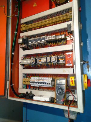
[Newbie] Electrical components

The transformer is there to power the coils on the contractors (relays) that control the motors. Typically control circuits are 24v.
Where do you see an indication of a DC circuit?
I see no rectifier bridge.
Some of the machines from the 40's and early 50's used 220 vac as control voltage!
 
Where do you see I said DC? or that circuit is 24v? I just said that 24v was a typical control voltage. My main point is the transformer is there to power the contractors, not a light.
 
Where do you see an indication of a DC circuit?
I see no rectifier bridge.
Some of the machines from the 40's and early 50's used 220 vac as control voltage!
Some contactor control circuits did use DC from a rectifier, but most I have seen have 24V AC coils, and the 24V AC was the voltage running through the E-Stop and control push-buttons. The motivation behind this design philosophy was to have all panels a user could touch be totally free of carrying anything wired to the live mains. E-Stops could also be all over the place. It had to be safe enough to put your hand on even when wet.
I still avoid high energy mains switchery directlly on components on any panel I touch.

Going "simple" for anything with a reasonable power inductive motor was not really an option if the switch contacts could weld up - and they do. Other arrangements are seen as "ghetto" hang-togethers. Small bench grinders do tend to have a straight mains switch. Drill presses also, but use a designed robust rotary, with really big fat contacts built to handle a bad time making disconnections.

DC circuits

DC circuits required pay attention to relay and contactor coils. Various hardware was "polarized", requiring connection to the correct polarity. It would involve diodes across the coils, to suppress the voltage spike. In normal connection, the doides would be reverse biased, and so be "not there" so far as the normal applied voltage was concerned. Upon switch-off, they would shunt the reverse EMF spike.

LINK --> Why is there a diode connected in parallel to a relay coil?

Another reason for using DC was to allow a diode-based scheme for "driving out" of safety limit switches. It's a darn pain if one has inadvertently driven a machine into a limit switch, and be stranded there, unable to get it to move in the direction to recover. Very simple diode steering circuits get one out of this, but of course, need DC to work. Many factory machine circuits had two limit switch sets. The first could be recovered by simply driving out. The back-up required maintenance attention to discover the fail, because the machine might be driving lead-screws, and capable of rearing it up out of the floor! I preferred to remove a thread from near the end of the leadscrew, so things would run out of ability to move before things started bending.
 
So you have a Vfd for the grinding spindle...what are you going to run the pump from? It is also 3 phase.
You can see the control transformer reduces the 3 phase hi voltage to a single phase low voltage....115 vac.
Control voltages are just that a lower voltage circuit almost always single phase meant to control the functions of the machine.
Older machines generally used 115 vac.
It wasn't until later that the use of DC control voltages started being used.
Avoid over complicated circuits on this simple unguarded machine.

I’m still debating my coolant pump options.

The coolant tank is welded 1/4” plate and with the attached pump weighs probably 80-90 lbs so it’s very hard to move. It’s also completely inaccessible because it slides into the back of the base.
So to use it I need another VFD.
It would be simpler to just put in a standalone pump and tank.
 
Turkish
 

Attachments

  • 20201223_184046.jpg
    20201223_184046.jpg
    1.9 MB · Views: 10
Last edited:
I find very few 24 vac control circuits, they seem to mostly be on European built equipment.
Last week it was a Turkish made machine, but I know several of the older Polish, Chech. Machines I maintain are also 24 vac control voltage.
 
Why not use this panel to mount your new components on?
Is it deep enough for your teco?
This could be a pretty panel inside while looking original on the outside.
You dont need to vary the motor speed so your existing switches should work on the tecos 24 vdc internal control circuit.
If deep enough for your drive then strip it and paint the inside white.
Decide whether you want fuses or circuit breakers .
Interesting idea. I'll measure it and see. The Teco is quite deep as it happens and my gut says its too deep for the panel.
 
Hi David, I don’t own nor have experience of surface grinders but it is on my ”So cool I’ve got to get one” list. A question - what’s the purpose of variable speed? Does it affect the surface finish?
 
Hi David, I don’t own nor have experience of surface grinders but it is on my ”So cool I’ve got to get one” list. A question - what’s the purpose of variable speed? Does it affect the surface finish?

Honestly my experience and knowledge of surface grinding is only slightly more than being able to spell surface grinder and identify one at 50 paces.
I have read that slower wheel speeds can benefit certain grinding situations but I cannot recall the specifics.
 
Back
Top