Time to have a think about things like E-Stop, and services like coolant pump, and exactly what features are provided on your VFD besides a knob speed control. Sure - you can just bypass all the previous stuff, and use the VFD like it's a model train controller, but it helps to check before you start cutting wires.
First is to understand what you have got, and what you should retain. There absolutely has to be an isolator switch upstream of the whole lot. Usually, there is one on the wall, but often there is a rotary type, fully rated switch on the machine as well. That has to be kept.
Things with "starts" and "stops" have latched contactors. For you, the coolant pump contactor, and circuits would be retained.
The motivation for using contactors of that construction for switching to induction motors is because of the motor's excellent ability to turn switch contacts into a welded up mess when switching the motor OFF! Suddenly disconnecting the forward current leaves the motor spinning as a generator with inertia, and the energy stored in it's magnetic fields will make a HIGH voltage, and try to spark over an arc. A contactor has a pivoted bar with a switch contact at both ends, which interrupts the current in a way that the arc cannot get going. When the control of the current is via solid state semiconductors (i.e. VFD), that problem goes away.
The general start-stop method is to have the (momentary normally open) start button power a contactor coil which has a separate relay contact on it devoted to "holding itself on", or "latched". It allows to let go of the start button. The "stop" pushbutton is a momentary normally closed type in series with the latching contact, allowing it to "drop out", and come to a stop. This "stop" circuit is also put in series with a mechanically latched E-Stop, with a big flat red knob, that gets re-set with a twist or a tug. The whole philosophy here is not to have a situation where the machine is switched on like a light bulb, and can end up hung in a switched on state doing massive damage, mangling your face from a caught-up shirt, whatever, with welded together switch contacts prolonging the mayhem!
The "ENABLE" on your VFD
It is usually there somewhere. Most have buttons direct on the case, but if to be controlled from external ON and OFF switches, have connections for that. The good ones are safety rated such that an E-Stop switch can be wired to the ENABLE, guaranteed to stop the drive, and render the motor connections so safe that you could work on it's connections (I would never trust that)! Similarly, there can be places on the VFD to connect your START and STOP switches.
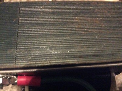
As example, here is a picture of an (old) motor controller I have diverted from being trashed.

You can see the row of buttons to start, and stop, and setup. You can also see the other terminals to hook up to external buttons for start, and stop functions.
Your surface grinder
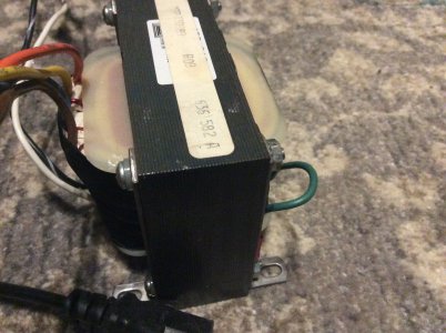
Getting your kit right should be quite easy. Probably the most important check is to know what the transformer does. Sure, the contactor for the grinder motor is now replaced by VFD, but you might want to retain START and STOP, etc push-button switches. Just add a extra hole for the external speed control potentiometer.
My bet is the transformer supplies the isolated safe low voltage (usually 24V) for latching the coils of the contactors, putting through E-Stop safety circuits, and stuff like that. These transformers also supply the power to light up the indication lights. Usually the ON running bulb is powered from across the contactor relay. Your VFD may have an ON state output for this, or a output that can drive a relay to light it up.
The wiring diagram and instructions for your VFD may be a good start. While I am sure I could get enough indications from the display of the example drive in the picture, I would be seeking to have it hidden away in the control enclosure, and it can light up external lamps, and respond to external push-buttons that were there on the original kit.