Die Filer - have one or insights?

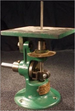
I have one just like Greg's (F350ca) got the castings from MLA, it was a great project to build, I don' t use it much but its handy and was a fun project to build a dozen years ago or so. Very good plans and castings, I suspect anything from MLA is a winner.
 
I have one just like Greg's (F350ca) got the castings from MLA, it was a great project to build, I don' t use it much but its handy and was a fun project to build a dozen years ago or so. Very good plans and castings, I suspect anything from MLA is a winner.
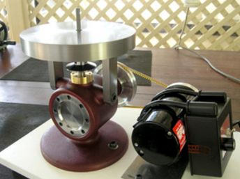
What drive did you use with it? Chris of Clickspring used a 1/2hp Sherline motor with speed control and it looks like a nice solution. Here's a photo of his MLA.
upload_2017-8-31_20-25-41.png
 
I used a half horse Craftsman motor that has been following me around for 40 years, gross overkill but it gets job done, 1725 rpm. with small pulley on motor
 
Maybe not to the same standard, but this reminded me of a dirty little application I saw once from somebody who didn't have a scroll saw. They drilled a hole in a table and screwed the table of a jig saw to the bottom of the table so a blade stuck up thru the hole.
 
Thanks for all the feedback here. After pondering the options, I have decided it would be fun to make one. So I bought the casting set from MLA.

So I am about to make a big mess machining cast iron. When I get it finished, I will post the outcome on a thread of its own.

Now to look into the ends and outs of machining cast iron.
 
I have 3 die filers,and STILL bought the Lathe Accessories kit,because it makes such a beautiful little filer. You can make your own files by cutting regular small size files off,grinding the tang down to slip into a 1/4" cylinder,and using J.B. Weld to glue it into the 1/4" cylinder. This is what the kitb recommends,and JB dries hard as can be! Great stuff.

I put a variable speed motor on my Butterfly because ALL die filers run WAYYYYY TOOOOOO FAST ! This not only gets your finger tips snapped,but it wears out the files too rapidly. Just like cutting metal with too fast a bandsaw speed,or running a lathe too fast on tool steel,files aren't made to run excessively fast. The die filer becomes MUCH safer and more easily accurately controlled if you slow it down. Makes a HUGE difference. Penn State catalog sells a little 1/2 H.P. motor WITH variable speed box for about $119.00. That is PLENTY of power even for a Butterfly die filer. It'd be perfect for the little kit.
 
Thanks George for the input. I think you are spot on variable speed and slow.

I am familiar with the Penn State offering and have that as one of my options to study.

The other is the Sherline drive. The Sherline has far more turndown since it is a 90 vdc motor. Evidently you can turn it down to 70 rpm. But I do need to dig into the specs a bit more and understand its duty cycle at lower rpms. An advantage of the DC drive is that the torque is still very high at low speed. The cost is twice as much as the Penn State solution but it seems not too bad considering what you get.

EDIT: George, can you recommend some targets for strokes/minute?
 
Last edited by a moderator:
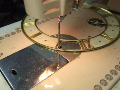
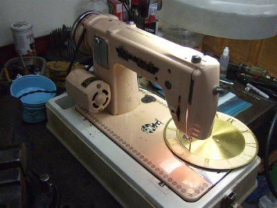
These are from the clock and watch forum I belong to and show a perfect re-use- the files are cutting on the down stroke and the sewing machine already is set for perpendicular action.

You do NOT get the pull away or the ease of setting the angle- but a jig can solve one of those problems!

I seriously envy you on the kit build- just trying to show how others "made it work" as well- best of journeys in the build and lets see pics!
SewMach Filer.jpg SewMach Filer2.jpg
 
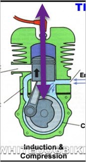
I'll give a guess here, kinda based on general principles ... Note that the "traditional" slide mechanism allows guide bearings on the vertical rod both above and below the rotary > linear mechanism. This makes for a stiffer and more exact linear motion. A crank mechanism, such as on an engine, only allows the vertical motion to be guided (by the cylinder) on one side of the crank. So it will take more vertical space - including a certain minimum height of the piston for it to be guided. In addition, there's a lot more frictional area on such a piston than on the guide rod of a traditional die filer.

Now say you built a crank mechanism that was offset behind the rod - so you could put bearings both above and below the crank linkage. You'd still need extra vertical space for the connecting rod. If the rod swung through an arc of +/-45º, it would require extra vertical space about as tall as the stroke.

Try thinking of the slider mechanism as a "zero length connecting rod" design.
 
Back
Top