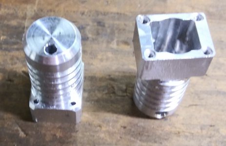
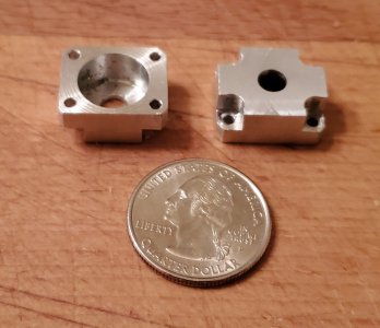
Converting my old pneumatic retracts to electric.

ONE DONE!!!!!!

Machining this part was an ordeal to say the least. But the first part is now finished (at least for this setup). One more setup to go to drill a cross hole at the small end. That should be quick and easy.

But before I tear down this setup I will make the other housing. Hopefully with no drama.

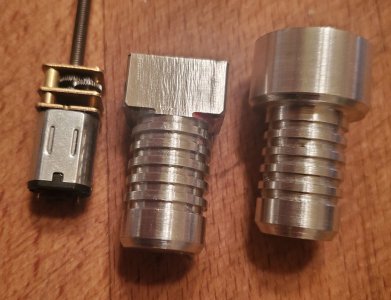
This Pic is with the motor and gearbox slid into place along side the next part that has had all of the exterior turning finished.
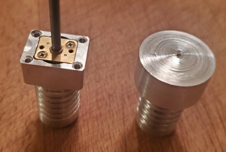
20240305_090350.jpg

This pic is a top view to show the internal machining and those pesky M2 holes. The motor gearbox is along side for comparison to the internal machining. You can see the offset hole at the bottom where the motor wires will come in. There is plenty of room at the bottom for the motor terminals, wiring, and a filter capacitor.
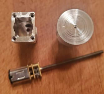
20240305_090455.jpg

Side view of all the parts. The surface finish does not look as bad as this lighting angle makes it look. Odds are that if you are looking at this on a computer that the image on your screen is way bigger than the parts are, this housing is only 1.375 long and the round finned part is .620 Dia.
20240305_090530.jpg
 
Last edited:
You can kind of see something that I often do on parts that start round and end up square. The dia of the turned "head" is set so that once the sides are milled the corners are actually the head dia. this way they come out chamfered with out any extra setups for chamfering Also there has been no deburring done yet, That will be later.
 
good job on the rescue! Working at that scale is way harder than bigger stuff, up to a point I guess. I didn't want to preach, but I've had far more success drilling out broken hard stuff with a carbide endmill than a carbide drill. Almost every time the carbide drill has snapped, whereas most times the endmill survives for another fix.
 
good job on the rescue! Working at that scale is way harder than bigger stuff, up to a point I guess. I didn't want to preach, but I've had far more success drilling out broken hard stuff with a carbide endmill than a carbide drill. Almost every time the carbide drill has snapped, whereas most times the endmill survives for another fix.
By all means, preach away, that is why I am posting, so that I can learn from others that have been there and done that and someday this may help someone else to learn from my errors. This was my first time breaking off a drill bit in the hole that had to be extracted I did not know what I was doing, just fumbling along.

Had I tried the end mill first it would have been a 1/16 end mill with a 1/2 in length of cut. That is what I have in my drawer and the shoulder that was being drilled is 7/16 deep. After the hole was egged out I used the "big" 3/32 end mill to clean up the hole.
 
yeah a 1/16" endmill would have been butt puckering. You can use one to pilot a hole though - most times my carbide drill have snapped due to wandering off an irregular surface
 
Well the second part went with no drama.

Still took a day and a half to machine it.

Now just have to drill the one cross hole in each one and this part is done.
Pics coming as soon as they are done debured and cleaned up.
 
FINALLY finished the housings. After the previous shenanigans they went quite smoothly.
Gave them to a friend that watched me do the thread repair on the first one and he could not pick out the one that was repaired with the parts in his hand.

20240316_095353.jpg
 
Next up are the caps that bolt to the end of the housings with four M2 cap screws, and hold the bearings to support the output shaft.
I posted pics of the turned portion back in post #33.
They were first mounted on the mill with the small end up, Then were milled for the rectangular shape and the holes for the screws drilled, then flipped over in the vice and the big end was milled off to final thickness. I would post a pic but they are buried deep in the vice and not much to see, just a few thou sticking above the vice jaws. Just have to put in the c'bores for the screw heads and they will be done.
But as it seems to be my methodology of sabotaging myself, I forgot to order a 4mm cutter to make the c'bores. SO now the mill is tied up until the cutter gets here. Shouldn't take more than 10 minutes to pop in the c'bores, once the cutter gets here.
 
And here are the pics. All of the parts do need to into the parts washer for a good bath. The pics make them look a lot worse than they really are. The pocket is for a 1/2 x 3/16 ball bearing. The 4 screw holes are for M2 screws.

20240318_171322.jpg
 
Now the fun part. I have been putting it off but have run out of other parts to make, so I guess the time has come.

The Trunion it is pictured in post #11 and the CAD model pictured in post #13.

My choices are to modify the existing trunions by cutting a deep slot for clearance of the motor drive shaft, or make a whole new one from scratch. Cutting the slot would be fairly quick and not to difficult. But the existing trunions are fairly worn to the point that for a few years I have had to add shim stock to make them fit correctly. So the obvious other option is to remake new trunions from scratch.
To make new would take setups from many sides and angles. The originals were started from an extruded custom shape. I would have to replicate all of that.
Time to actually make drawings and see if I can figure out an order of operations and all of the fixturing to hold it for all of the ops. I still have plenty of material left from the original bar of 7075. it is 30mm dia so that is where I would be starting from.
 
Back
Top