-
Welcome back Guest! Did you know you can mentor other members here at H-M? If not, please check out our Relaunch of Hobby Machinist Mentoring Program!
You are using an out of date browser. It may not display this or other websites correctly.
You should upgrade or use an alternative browser.
You should upgrade or use an alternative browser.
Controlling Stepper Motors
- Thread starter gwarner
- Start date
Just an update on my small CNC build. I’m still waiting on the slow boat from China to deliver my motor controllers. I believe I have everything else I need.
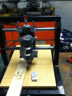
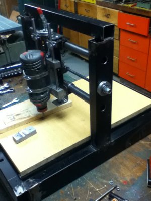
Below is an image as it sits now. I guess you could call it a mini mill. It is 18x27 inches long. I made it from a scrapped tread mill. The X and Y runners are ¾ black iron pipes that I polished on my wood lathe using a belt sander on the initial steps. (Don’t try this on your metal lathe as it makes a mess). I used 1” pipe for the slider bearings. The z axis is 3/8 rod from the machine I got the steppers from.
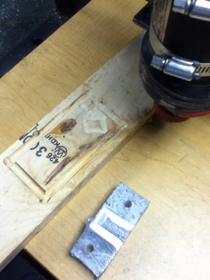
I hand fed some wood and then screwed a small block of aluminum to the table to run it through. Both cut and fed well with the ¼ bit I had chucked up. I have no intent to use this for aluminum. It was just a test on the rigidity of the machine. I say it passed as the last cut was pretty deep. To be honest I did not think the roto zip had that much power.
For lead screws I used 3/8 all thread and it turns very nicely. I still need to determine how I am going to drive them via the motors. It will depend on if they have enough torque. Otherwise I may have to look at gearing. From my readings, I may discover Backlash may be a problem for me as well. Seems Delrin nuts may have to be made.


- Joined
- Jul 23, 2014
- Messages
- 347
quick cheap way to connect motor to shaft for the kind of torque you would be looking at would be flexible shaft couplers http://www.ebay.com/sch/i.html?_odk...ng.TRS0&_nkw=flexible+shaft+coupling&_sacat=0
Timing belts an pulleys are nice for changing your gearing but will cost more. Looks like you have access to welding so it shouldn't be too difficult to tack on a bracket for the motors.
Mach3 has backlash compensation so you can make up for some amount in software. If you write your own code, 500 lines will get you pretty far.
Well I got my controllers in yesterday and have hit a wall. X is the only axis that will work. I need to know how to determine if it is the cable, the breakout board or the software. I know the motor controllers are OK as if I connect then to the x pins they work but nothing will work on z or y.
I have tried every possible combination I can think of and nothing happens on the z or y axis.
The configuration files all appear to be good from what I can tell.
I am at the point thinking the breakout board must be defective. I have ran out of things to try.
I just ordered a new 25 pin serial cable since I can't confirm the history of my current one. (possibly null modem?)
Anyone have any additional suggestions for me to solve this?
The good news is the motors seem to have enough power to turn the lead screws directly.
- Joined
- Feb 8, 2014
- Messages
- 11,144
Could be the cable or the breakout board. The cable you want is a serial extension cable, they are wired straight through. What software are you using?
 I'm surprised!
The good news is the motors seem to have enough power to turn the lead screws directly.
 I'm surprised!
The cable I pulled out of a bin at a old computer store. It was one of the few I could find that had the proper ends. It does make the "Ready" led light up on the breakout board when I connect it. I had a cord from and old zip drive with the correct ends but it wont recognize at all. I did plug the board straight into the computer and it did not seem recognize/work either.
I am using linuxcnc.
I am using linuxcnc.
- Joined
- Feb 8, 2014
- Messages
- 11,144
I did plug the board straight into the computer and it did not seem recognize/work either.
I guess that pretty much eliminates the cable as the problem. I can't help you with LinuxCNC, never seen it before. I would go through the setup screen(s) again.
I have been through setup screens since yesterday at about 4pm until midnight and again this morning until I gave up.
I think it is a bad board but am looking on input on how I can test that.
Pins 2 and 3 (x) have .13 volts and fluctuate to 5 volts when running test axis. Pin 4 has 5 volts constant and pins 5,6,7 all have .13 volts and don't change no matter what (4 and 5= Y 6 and 7=z). Should pin 4 be reading 5 volts????
The board is clearly labeled with the pins. Anyone know of a site that shows info on testing these boards. I can follow a wiring diagram but electronics is one of my many weaknesses.

