Cincinnati Toolmaster 1-A

With that many separate motors (envious) you're best option my well be an RPC. Then you can use all of the machines original controls, only losing the variable speed of the VFD.

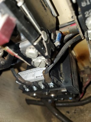
For the VFD, on the wiring diagram ignore everything except for the five motors on the extreme right. Each motor has three lines xT1, xT2, xT3 where x equals the motor number. Now, in the electrical box in the back of the machine there is a long terminal strip on the right side. Each position is labeled. One side will go to the motors (on mine it's the right side), the other side goes to the contactors/controls. You need to disconnect the control side, then bring your VFD lines in and daisy-chain down the stack.

L1 -> 1T1 -> 2T1 -> 3T1.......

Same for L2 and L3 to the xT2 and xT3 positions.

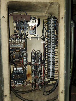
Addendum. Look at the top left of the wiring diagram. That is a map of the physical layout inside the electric control box. The "Circuit Interuptor" at the top is the keyed switch at that is controlled by the access hatch lever. The outside lines come into this. You should then be able to bring the LL1-2&3 straight over to xT1-2&3. Done this way, the original power lead can be used for the VFD. Just don't open the hatch door while the vehicle is in motion.

Thanks Randy! I'll look at your wiring scheme and think it over. It would be nice to have a VFD on the motor since that toothed belt is such a pain, but then again a bit more work in wiring and not as plug & play. The circuit interrupter you mentioned has a stranded wire tied around that extended pole that the hatch connects to, on my machine. Maybe that's why the contactor was tripping.

There is nothing wrong with having two VFDs especially if you allready own One??? Millions of machines out there have 2 VFDs. Some have dozens. Much cheaper, power efficient, and space savings than a rotary phase converter in your situation.

You can wire current controls to actuate the VFD, little hard to suggest how here as there are so many ways, or you can use the face plate of the VFD to control the motors. But yes, as mentioned before, the motors themselves should be direct wired, NEVER through a drum switch.

You do NOT use a single VFD to run two motors unless they are equal size and very similar outputs, which I highly doubt your power feed motor is anywhere close to the spindle motor.

This is what I was wondering about. In my case, it would be 4 VFDs (spindle, the 2 X&Y feeds, and coolant). Though, maybe you're right actually. If one VFD can power both powerfeeds (they're both 1/4hp, same motor basically), then I could just forgo the coolant motor and use 2 VFDs.
 
This is what I was wondering about. In my case, it would be 4 VFDs (spindle, the 2 X&Y feeds, and coolant). Though, maybe you're right actually. If one VFD can power both powerfeeds (they're both 1/4hp, same motor basically), then I could just forgo the coolant motor and use 2 VFDs.
Most manufactures of VFD have set up instructions for two motors. Some of the manuals are long and have literally 100's of parameters that you wont use but are chocked full of info.
 
1b owner here too, I went with the 2 VFD's, removed the switch guts on the spindle motor and replaced with a 3 position maintained, removed all the electrical stuff. The table drive is i think 1/4 HP so the VFD for that is not expensive since you already have one for the spindle. I just run the table drive at 100% and can vary the spindle. Oh I ran a 4 wire shielded cable from the spindle switch through the conduit. the box to get into the casting lifts right up by taking a set screw loose I was able to pull the cable through using the wiring that is there pull a pull wire in then pull the original wire back through with the shielded cable.

Phil
 
just saw that you have both drives, nice, I'd use the same VFD for both since these just run forward and you don't really need to vari the speed.
 
Thanks for the ideas guys. Before I commit to more VFDs or an RPC, I was digging around in the back wiring panel and realized for the first time that the back cover says the machine is wired for 440V. It also has the s/n which dates this to 1957 (and the circuit interrupter in the top left says May 1st 1957).

However, on the internal transformer to 110V, the high voltage leads on the top are set up for 230 and not 460V. I was wondering if this means it's really wired 220 or maybe the transformer is not the only thing which determines if it's wired for 220 vs. 440.
 

Attachments

  • 20220621_145522.jpg
    20220621_145522.jpg
    198.7 KB · Views: 17
  • 20220621_105846.jpg
    20220621_105846.jpg
    153.3 KB · Views: 17
  • 20220621_105740.jpg
    20220621_105740.jpg
    378.5 KB · Views: 17
I'd open one of the boxes on a motor and see what it is wired for, more of a true test I think.
 
I'd open one of the boxes on a motor and see what it is wired for, more of a true test I think.
Do you have the nameplate info/wiring diagram for the feed motor? Should be a 1/4hp Standard Electric out of Dayton OH. What I assume was my nameplate info was fossilized into black cardboard on the inside of the removeable plate.
 
here is the table motor
...Can't believe I missed the wiring diagrams on the outside! So I removed whatever that rubber protective coating was on the inside of the wiring box for nothing. Anyway, looks like both powerfeeds are 220V wired. I'll assume the motor is too for the moment since the transformer is also.

Possibly bad news today. I was tramming the head earlier, having to put shims inbetween the head and ram (one I'll never see again but the other I made sure to leave sticking out partially). Tramming the X direction, I noticed that when I tighten the quill lock, the DTI on the table moves 0.0015" closer to the side without the lock. Is the spindle/quill totally shot? Is this normal?
 
1B owner here. Following along looking to pick up all I can.

My belt isn't too bad to adjust as long as I give it enough slack.

Someday I hope to go to a VFD. Really interested in how you feel after getting done.


BTW, how did you figure out the year?
 
Back
Top