Cincinnati Toolmaster 1-A

allamateur

Registered
Registered
Joined
Feb 4, 2021
Messages
39
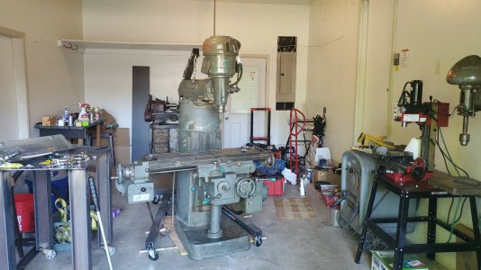
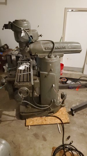
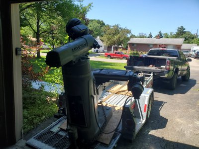
I just got this Cincy Toolmaster 1-A in yesterday. Some pics attached of it in the garage and being unloaded (you can also see the little mini mill it's replacing!). It was tough without a pallet jack or forklift, but with a HF crane, prybar, and some wooden dowel rods under plywood, it came slowly (and with a lot of teetering on the ramp...). Very scary affair at times and I eventually need to get it on a pallet and get a pallet jack so I'm not having to prybar it everywhere.

I'm having some mild troubles with it, the first of which is that the toothed belt at the bottom of the head is incredibly difficult to change to the low position, even with the rear set of pulleys pushed forward. It runs nice and quiet in the high position but I haven't been able to get it to the lower position. Is this common or do I maybe just have a short belt?
The other problem is that the contactor/breaker at the back keeps tripping when I have it powered (220V dryer plug thru to VFD). I can usually restart it by going to the side panel and playing with the start/stop buttons and the power switch, but I can't stop it tripping in the first place. Let me know if this is a common problem. It's got the X and Y powerfeeds, (some speeds work, others probably have broken gears but I haven't opened them up to see) and the coolant pump which works, so I'd rather not bypass all the circuitry back there and just wire the motor.
 

Attachments

  • IMG-20220617-WA0001.jpeg
    IMG-20220617-WA0001.jpeg
    523.1 KB · Views: 90
  • IMG-20220618-WA0003.jpeg
    IMG-20220618-WA0003.jpeg
    182.5 KB · Views: 90
  • 20220617_153223.jpg
    20220617_153223.jpg
    656.7 KB · Views: 89
VFDs have to be wired directly to the motor it is controlling with no switches or contractors between. All motor control is then done with the VFD. Usually the machines controls like forward and reverse, off and on are rewired to control the VFD.
 
He's right, you are taking a chance of blowing up your vfd unless it's wired directly to the motor- no switches or contactors in between.
If the machine has two motors the best approach is to use a rotary phase converter- then you can operate the mill with stock wiring
Otherwise you really should have another vfd for the feed motor
I guess you can keep your fingers crossed and keep using the single vfd- some are more rugged than others, but if it fails you'll know why
 
If the machine has two motors the best approach is to use a rotary phase converter- then you can operate the mill with stock wiring
This.
I recently did a VFD install on my mill but replaced my stock for/rev drum switch with new on/off, for/rev and estop switches.
 
Cinci 1B owner here. While the advise to wire directly to the motor is normally sound, it's not practical on a Toolmaster. There are two reasons for this. First is the drum switch is part of the spindle motor. It's not a simple 3-in 3-out switch, there are a zillion wires in that thing. Second is there are two three phase motors on the machine that run full time. One for the spindle, the other for the power table.

If you wire directly to the spindle motor, you lose the power feed.
If you use the VFD to reverse the spindle, you will also reverse the table directions.

What you do need to do is get around all of the Cinci breakers and contactors. Wire the VFD in such that it is a direct feed to the drum switch and the table control. Then follow two rules. NEVER change the drum switch with the power, and NEVER start or stop the table motor with the power on. I just leave my table motor running full time.
 
Thanks for all the info guys. I'm bummed about that, I had this VFD laying around from messing around with a 2hp 3ph Dayton motor I got for free. A RPC will run about $500 which is 1/3 what I paid for the mill, but I guess I can save up and just let it sit for the moment. I've got 4 motors on the thing, the spindle, X & Y power feed motors, and the coolant pump motor. Getting 3 more VFD's/static converters would be the same price and harder to wire than just an RPC. What rotary converters do you guys recommend?

The catch is, at the shop I bought it at, this contactor was jumping there too. They had it powered via a cart that had 220V 3ph leads coming off it, not sure if it was a static phase converter of some kind or what. I bought it with that knowledge and assuming that the jumping contactor would be an easy fix (at this shop, we just held a screwdriver to it to keep it closed). So the jumping doesn't seem to be due to the VFD, far as I can tell.
What you do need to do is get around all of the Cinci breakers and contactors. Wire the VFD in such that it is a direct feed to the drum switch and the table control. Then follow two rules. NEVER change the drum switch with the power, and NEVER start or stop the table motor with the power on. I just leave my table motor running full time.
I have no idea how to wire much of anything that has more than 3 wires, and the wiring diagrams on vintagemachinery.org are complex to me. That's why I wanted to avoid routing past that circuit at the back. Also, if your VFD is wired to 2 motors at once, don't you run the risk of blowing it? And by the way, do you have trouble changing your toothed belt?

The good news is that despite the contactor, it seems in decent shape. Maybe 9 thou backlash in X and 16 thou in Y. Table's a got some apprentice marks but not terrible.
 
Last edited:
Getting the toothed belt down onto the larger spindle cog is a bit fiddly, but part of that is because I have a tach speed pickup in there. I just use the VFD for slow speeds.

I'll look at the wiring diagrams and my machine to see if we can find an easy spot. My machine is different, it is a two phase model that was converted to three phase before I got it.
 
With that many separate motors (envious) you're best option my well be an RPC. Then you can use all of the machines original controls, only losing the variable speed of the VFD.

For the VFD, on the wiring diagram ignore everything except for the five motors on the extreme right. Each motor has three lines xT1, xT2, xT3 where x equals the motor number. Now, in the electrical box in the back of the machine there is a long terminal strip on the right side. Each position is labeled. One side will go to the motors (on mine it's the right side), the other side goes to the contactors/controls. You need to disconnect the control side, then bring your VFD lines in and daisy-chain down the stack.

L1 -> 1T1 -> 2T1 -> 3T1.......

Same for L2 and L3 to the xT2 and xT3 positions.
 
Addendum. Look at the top left of the wiring diagram. That is a map of the physical layout inside the electric control box. The "Circuit Interuptor" at the top is the keyed switch at that is controlled by the access hatch lever. The outside lines come into this. You should then be able to bring the LL1-2&3 straight over to xT1-2&3. Done this way, the original power lead can be used for the VFD. Just don't open the hatch door while the vehicle is in motion.
 
There is nothing wrong with having two VFDs especially if you allready own One??? Millions of machines out there have 2 VFDs. Some have dozens. Much cheaper, power efficient, and space savings than a rotary phase converter in your situation.

You can wire current controls to actuate the VFD, little hard to suggest how here as there are so many ways, or you can use the face plate of the VFD to control the motors. But yes, as mentioned before, the motors themselves should be direct wired, NEVER through a drum switch.

You do NOT use a single VFD to run two motors unless they are equal size and very similar outputs, which I highly doubt your power feed motor is anywhere close to the spindle motor.
 
Back
Top