Can anyone identify the vendor of this mill?

That VFD will be nice. I hope to put a VFD on in the future - if I run across a motor thats reasonable.

Single phase induction motors (the vast majority of them) can be converted to 3-phase by removing the (start and) run capacitor(s).
So, you should not have to switch motors just to get VFD.
 
Single phase induction motors (the vast majority of them) can be converted to 3-phase by removing the (start and) run capacitor(s).

Really? How do you do that?
I picture two wires from the motor and three from the supply..........neglecting all grounds/neutrals.....how does that work?
-brino
 
Pull up the grizzly manual:: http://cdn2.grizzly.com/manuals/g0730_m.pdf
and turn to page 39 and 40.

Here we see the wiring diagram that allows the motor to be switched from 120V to 230V. Notice that there are 6 wires coming out of the motor, and start and run capacitors <somehow connected to the motor. In the 210V configuration 3 of the motor wires are connected together, in the 210V configuration three (3) sets of wires are connected individually together.

NOTE: the terminal numbering in this manual does not correspond to the terminal numbering in ANSI motor wiring specs. But otherwise is illustrative of the dual voltage wiring.

{Aside: there are induction motors of low HP levels that are single phase only--for things like refrigerators,... We are not talking about these--we are talking about motors with significant power (> 1HP) but more importantly those that can be reversed in direction.}

Next pull up: http://css.wsu.edu/wp-content/uploads/2012/09/Motors1.pdf
and go to page 326 in the book, page 10 in the chapter PDF.

Dual voltage motors can be used in Wye (Y) style (fig 16-25) but can equally be used in Delta style as (fig 16-26). In the low voltage configuration coils are run in parallel, in the high voltage configuration coils are run in series. The Grizzly manual is showing the Delta configuration of dual voltage operation but in 120V<->210V whereas the PDF is showing 230V<->460V.

In the single phase configuration, a capacitor is used to create the third phase.
By gaining access to the third pole, and removing the capacitor, the reversible induction motor is perfectly happy to run on 3-phase power.

Running with a correctly spec'ed capacitor, the 1-phase version delivers 83% of the motors HP capability compared to the same motor running in 3-phase with the same voltages.

ETA: Question 12 at the end of the chapter illustrates the purported wiring of the motor in question.
My previous statement needs to be modified to include the ability to reverse motor direction. This implies that there are actually 3 phases of coils in the motor. Irreversible inductions motors need only 2 sets of coils, and always have to have a capacitor--these are typically reserved for low voltage (120V) and lower power, refrigerators, fans,...

My previous statement might also need to be modified to include the dual voltage option--but my EE training ended in 1975 and I can't remember.
 
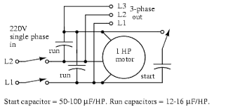
I found this simplistic picture on the web. While I have never done this, could it be as simple as removing the caps and connect the 3 phase like in the picture?
1523746987592.png
 
You have a picture of a 1-phase to 3-phase motor converter. Here you are using one motor to provide 3-phases to another motor.
I was explaining how to convert a 1-phase motor with start/run capacitor(s) into a (pure) 3-phase motor. Here there is only 1 motor.
But the underlying principles are the same.

A 3-phase induction motor needs no capacitors.
 
Um....that's not how I read it.

Mitch,
Both of those references do talk about "dual voltage" motors, ie. ones able to run from either 120VAC or 240VAC.
The Grizzly manual only talks about a single-phase motor.
The second one also talks about
1) how to convert a single-phase motor between the low-voltage and high-voltage configurations, and
2) how to convert a three-phase motor between the low-voltage and high-voltage configurations
But it does NOT say that you can turn a single-phase motor into a three-phase motor.

Boswell,
That picture looks like the standard "rotary phase converter" using a three-phase motor to generate a quasi-three-phase supply from a single phase input.

-brino
 
Last edited:
But it does NOT say that you can turn a single-phase motor into a three-phase motor.

No, it does not. What the Grizzly diagrams (near picture) illustrates is that the motor has 6 coils (not 2 for refrigerators). This is the necessary precondition for turning a 1-phase motor into 3-phase.

Now go to question 12 and look at the 1-phase diagram.

If you remove the switch (upside down U) and the capacitor ( -||- ) from the diagram and add an external wire to the 3rd coil, you now have a 3-phase motor.

Since the run capacitor is accessible outside of the motor, one HAS access to the 3rd coil even when one does not have access to the switch.

After one has the motor wired up for 3-phase operation, on then needs a 3-phase forward-off-reverse switch.
 
d

do you have a picture of toggle switch mounted and diagram of how you wired it up! that would make tapping a lot easyer! and where did you buy your toggle switch?

jwild1bill
I sent the info with a bunch of pics Monday morning to your email. Did you get them?
Jim
 
Back
Top