Bridgeport Motor Issue (Video)

I think you are using the drum switch between the VFD and the motor, and that is a HUGE NEVER DO for a VFD. You always hard wire the VFD to the motor. Switching while running causes huge voltage spikes, these exceed the transistor break down voltage. I'm guessing you blew up your VFD. And it should have error'd out on this. You may have been doing this for a long time, but I'm believing this finally failed.

Gotcha, didn't know that. But it looks like the VFD survived that mistake as it just ran my 3-phase belt grinder motor without a hiccup. When I get this resolved, I'll eliminate that drum switch. I'm assuming there's some other type of switch that can be wired directly in to the VFD to switch directions and turn on/off? The VFD is mounted on the side of my machine and would be a ***** to turn it on and off in its current location.
 
As pointed out, switching between a load and the VFD is not recommended. However, as it's running the belt grinder okay, you'd better look at the mill motor. Measure between each paired connection and the triple connection. They should be same resistance, but I'll bet they're not. Also check between the pairs. You can split the windings out and test in isolation, but this should be enough for a quick test.

Switching two of the windings is a common way to reverse a direct connected motor, but not the with a VFD. The VFD itself is capable of running the motor reverse, with no switches in the circuit. You can get a remote for most VFD, which allow control when the unit is remote mounted like you have, which is not uncommon.
 
OK, have you used an ohm meter to motor ground for each of the 3 leads? That's the other issue with large voltage spikes they can break through the winding insulation and produce a short connection. Also look for any frayed old motor leads or your splices and verify they have not gone to ground.


I have not, that will be my task for tomorrow morning. Several have mentioned testing the resistance on the windings. I'm still trying to get a clear picture of what exactly im testing. As mentioned prior, I believe 6-5-4 are connected together and 9-1, 8-2, and 7-3 are connected together. Am I testing those bundles of wires against each other or testing each of those bundles to the casting of the motor (ground)? What should I be seeing? I guess I could go to google and search for how to test a 3-phase motor also.
 
As pointed out, switching between a load and the VFD is not recommended. However, as it's running the belt grinder okay, you'd better look at the mill motor. Measure between each paired connection and the triple connection. They should be same resistance, but I'll bet they're not.

Switching two of the windings is a common way to reverse a direct connected motor, but not the with a VFD. The VFD itself is capable of running the motor reverse, with no switches in the circuit. You can get a remote for most VFD, which allow control when the unit is remote mounted like you have, which is not uncommon.

Gotcha, test the paired to the triple. Will report in tomorrow with the results.
 
I have not, that will be my task for tomorrow morning. Several have mentioned testing the resistance on the windings. I'm still trying to get a clear picture of what exactly im testing. As mentioned prior, I believe 6-5-4 are connected together and 9-1, 8-2, and 7-3 are connected together. Am I testing those bundles of wires against each other or testing each of those bundles to the casting of the motor (ground)? What should I be seeing? I guess I could go to google and search for how to test a 3-phase motor also.
As Lo-Fi said, for lead testing.
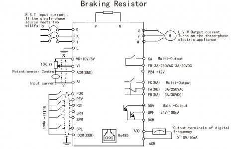
You can make the VFD use low voltage discretes and wire this to the drum switch, so it still controls the motor, but there is no high voltage going to the drum switch. You need to look at the manual for the VFD, it should have a 3 wire connection, a common power or ground wire (DC +12 or +24, or ground), and one of the discretes for Forward, and another for Reverse, your drum switch makes the connection. This needs 3 wires. And not to be confused with the 3 wires start stop type common connection.
I'm assuming you have a Hyangyang VFD, but that's a guess, I've attached the manual in pdf for that, and a diagram. Note the lower left side of it for the FOR/REV external discrete control.
Dang, manual was too big to attach.
Hyangyang diagram.jpg
 
As Lo-Fi said, for lead testing.
You can make the VFD use low voltage discretes and wire this to the drum switch, so it still controls the motor, but there is no high voltage going to the drum switch. You need to look at the manual for the VFD, it should have a 3 wire connection, a common power or ground wire (DC +12 or +24, or ground), and one of the discretes for Forward, and another for Reverse, your drum switch makes the connection. This needs 3 wires. And not to be confused with the 3 wires start stop type common connection.
I'm assuming you have a Hyangyang VFD, but that's a guess, I've attached the manual in pdf for that, and a diagram. Note the lower left side of it for the FOR/REV external discrete control.
Dang, manual was too big to attach.

Dude! Thanks so much. I completely understand what you're saying about just sending a low voltage signal to the VFD to control VFD operations; just haven't done my homework and read the manual. I need to. I have a lathe that's about ready to get a new 5hp motor and I'll need to be able to wire in the VFD to allow for use of the switches that control powering the machine from the apron. I'll start reading up.

Here's the VFD...I just went back in my Amazon order history and found it. I have the manual in the garage.

 
Ok here's the updates. I'm not sure what motor I was remembering but this thing definitely doesn't have 9 wires like the motor plate indicates. All I'm seeing is 3 wires. See attached pictures. I tested resistance across each of the three wires and got a constant value of 12.5 ohms. I tested each wire to the motor housing (ground) and got OL (Open Line) for that test, which is what you would expect with a good motor. I'm baffled.

For one, the plate on this motor suggests it has 9 wires and a low/high voltage wiring option. I'm seeing 3 wires. And even with 3 wires, there's no wild variation of resistance across the windings and there is apparently no grounded winding.

So....what do I have on my hands here?
 

Attachments

  • IMG_2888.jpeg
    IMG_2888.jpeg
    1.7 MB · Views: 16
  • IMG_2889.jpeg
    IMG_2889.jpeg
    1.6 MB · Views: 15
  • IMG_2890.jpeg
    IMG_2890.jpeg
    1.8 MB · Views: 20
Puzzling, but probably good news for your motor... Could you post the data plate from the motor?

I'm guessing the grinder isn't anywhere near the hp rating of the mill, so that might be a false positive on the VFD having survived it's outputs being switched. I'm trying to think up ways to test it...

The grinder motor is actually beefier...it's 3 HP as compared to the 1 1/2 HP on the mill. Here's the data plate.
 

Attachments

  • IMG_2886.jpeg
    IMG_2886.jpeg
    1.8 MB · Views: 18
Ok here's the updates. I'm not sure what motor I was remembering but this thing definitely doesn't have 9 wires like the motor plate indicates. All I'm seeing is 3 wires. See attached pictures. I tested resistance across each of the three wires and got a constant value of 12.5 ohms. I tested each wire to the motor housing (ground) and got OL (Open Line) for that test, which is what you would expect with a good motor. I'm baffled.

For one, the plate on this motor suggests it has 9 wires and a low/high voltage wiring option. I'm seeing 3 wires. And even with 3 wires, there's no wild variation of resistance across the windings and there is apparently no grounded winding.

So....what do I have on my hands here?
Seems if the actual motor does not match the nameplate, I would guess it had been rewired by a motor shop in the past.
It does not make sense that the VFD drives the grinder but not this motor. All you did was paint it? Just the exterior, and did not split the bell housing off like you have for the photos? Have you tried running the motor with without connecting the shaft to the machine?
 
Back
Top