-
Welcome back Guest! Did you know you can mentor other members here at H-M? If not, please check out our Relaunch of Hobby Machinist Mentoring Program!
You are using an out of date browser. It may not display this or other websites correctly.
You should upgrade or use an alternative browser.
You should upgrade or use an alternative browser.
Atlas TH42, My rebuild thread.
- Thread starter Phonnold
- Start date
- Joined
- Dec 25, 2011
- Messages
- 10,511
Steve,
Not necessarily. But when acting on my answer could have unfortunate consequences if I'm wrong, I try to remember to put some weasel words in. I've been wrong at least twice this year. :whistle:And your comments on the QCGB were quite correct. The distance that the carriage travels in one spindle revolution is independent of the spindle RPM.
Robert D.
schor, I thought about the QCGB comment later and realized I was thinking on that wrong.
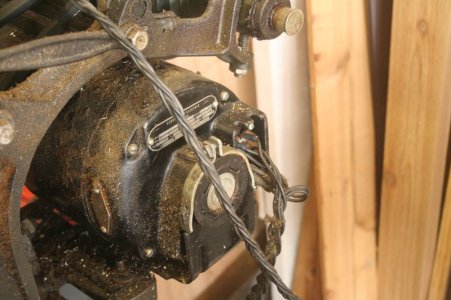
wa5cab, Thanks for the info, that kind of feedback is what I was looking for, even if it isn't what I wanted to hear. I will poke around and see what I can find in regards to either a motor replacement or a controller replacement. Was hoping to avoid that expense, but guess not. When I think DC motor I think of a positive and negative connection and that is it. This motor has much more than that, think there is 6 connections. 4 on studs and 2 wires that have been extended to the plug for the controller. This is the best picture I have of the motor on me, can get better ones tonight if need be.

The controllers I am seeing just seem to be a two wire hook up, so not sure they would work. Is there a "type" of controller I should be looking for?
Philip

wa5cab, Thanks for the info, that kind of feedback is what I was looking for, even if it isn't what I wanted to hear. I will poke around and see what I can find in regards to either a motor replacement or a controller replacement. Was hoping to avoid that expense, but guess not. When I think DC motor I think of a positive and negative connection and that is it. This motor has much more than that, think there is 6 connections. 4 on studs and 2 wires that have been extended to the plug for the controller. This is the best picture I have of the motor on me, can get better ones tonight if need be.

The controllers I am seeing just seem to be a two wire hook up, so not sure they would work. Is there a "type" of controller I should be looking for?
Philip

- Joined
- Dec 25, 2011
- Messages
- 10,511
Philip,
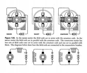
There are four basic types of DC motors - Series, Shunt, Compound, Permanent Magnet. The Series type is AC/DC, is sometimes called Universal, and is seldom found in sizes above about 1/10 HP. Your motor is compound wound, and is the only one of the four that should have 6 wires. The permanent magnet type only has two wires. The series and shunt will have two if they are not intended to be reversible (the four wires are tied together internally) or four if they are reversible.
The two-wire controllers that you have found are most likely all for permanent magnet motors. They will run the other three types but the Reverse switch on them will not reverse the motor. The one that you would want should say for compound wound motors. If all that you can find is one for shunt wound motors, this will work but you will have to outboard the reversing switch.
Two wires will go to the armature. Two will go to the series field. And two will go to the shunt field. I can't really think of a logical reason for yours to have 4 studs and 2 loose wires instead of 6 studs. If the motor is going to be reversible, you have to flip both field windings. Below are stylized wiring diagrams and schematics of the first three types.
If you cannot ID which of the three windings the studs and wires go to, using an ohmmeter, the series winding and the armature will have very low resistance. The shunt winding will probably be several thousand ohms. To differentiate between series and armature, pull one brush to ID the armature.
Note that to reverse the compound wound motor, you either reverse both windings or the armature. Reversing the battery will not reverse the motor.
Also, the drawing below, which originally came out of a WD training publication, had an error on the shunt and compound wiring diagrams. I corrected the error by moving the battery connection to the right end of the shunt field winding from the positive to the negative battery terminal.
Robert D.

Last edited:

