ArizonaCNCKits PM833 conversion now avalible.

I did take the column off originally thinking It was a necessity after having watched Dr Dflo's video on the old heavy metal kit. But after putting the column back up we found that the slide for the head would come off and on the column without having to unbolt the it. I would say if you are ordering this kit, plan on removing the column but try removing the slide before you you actually loosen the bolts. If the slide comes off without removing the column then it is not necessary. The ball screw will go in without having to remove the column from the base.

Unfortunately I did not weigh the head, I dont have a scale here at home, but it is heavy. It probably weight between 70-80 pounds alone without the motor.
 
very neat install, I particularly like how thorough you were with the oil lines.

A counterweight doesn't just aid the stepper/ servo motor on the Z axis, it also allows higher accel/ decel rates plus it helps remove stick-slip as the weight of the head isn't cocking the Z slide away from the column. You can use gas struts (car trunk lift struts are popular) or a counterweight with pulleys. I did that on my drill press table and it makes it super easy to move up and down, even with alot of weight on it. I used cans filled with melted lead as my counterweights.
 
............. Everything is double ball nut, X and Y are a 25mm ball screw and z will be available with either a 25mm or 32mm option.......

Are you sure about the X and Y being 25mm?

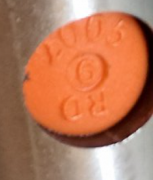
I zoomed in one of the images you posted and it looks like it has 2005 on the ball deflector.
20mm diameter
5mm pitch

2005_zoom.PNG

Did you have to take the column off of the base to install the Z ball screw?
By any chance did you weigh the head when it was off?

The column can stay on, I have removed my saddle numerous times while prototyping my DIY version. The stand I made has a open top which makes it easier to install the ballscrew as well. I still have the head off so i will try to weigh it I can come across a scale.

Eric
 
Spent most of the weekend trying to finish this up. most of the time was spent trying to dial in movement and backlash on all axis as well as making sure the head is in alignment. She is almost done all that's left is to make sure the head in in alignment across X and it will be usable.

Buzz, you are correct. That is my bad. I double checked the ball screws while I was under the machine and they are 20mm. I think the confusion was came into play when Dave was out test fitting parts, there was a lot of talk about different size ball screws on the different axis I must have got the numbers jumbled up in my head when I posted this. My bad.

All that's left now are a couple of things that will make the setup more automated like computer controlled spindle speed and touch/tool probe. So as of right now I have spindle forward/reverse hooked up thru acorn. That was super simple on the spindle motor controller that comes with the PM833, right now I am trying to figure out how to tie in spindle speed control. So until that happens I am kind of stuck with the adjustable pot hanging out of the side of the cabinet. But it does work as it sits. I had it running the other night for about 30 minutes, there isn't any real good break in procedure in the manual just a brief statement to start at about 50 RPM and slowly run it up the the rpm range. So I started at 50 for 5 minutes then went up in a few steps (500, 1000, 1700 and so on) leaving it at each speed for 5 minutes until I Had it at max RPM.
 
All that's left now are a couple of things that will make the setup more automated like computer controlled spindle speed and touch/tool probe. So as of right now I have spindle forward/reverse hooked up thru acorn. That was super simple on the spindle motor controller that comes with the PM833, right now I am trying to figure out how to tie in spindle speed control. So until that happens I am kind of stuck with the adjustable pot hanging out of the side of the cabinet.
a few months back I tried contacting PM about it but they gave me a *******t reply about proprietary information blah blah blah.

From what I gather its a 0-12v signal which sucks because most analog outputs 0-10v. I see the acorn device has 0-10v analog ouput so one option is to use an operational amplifier (OP-AP) as a voltage buffer. The op-amp will take the 0-10V output from your device and amplify it to the 0-12V range required by the motor speed controller.

I think the stock controller supplies 12v out one wire through the potentiometer and back into the board on a different pin. that pin reads the voltage which tells the controller how fast the motor should spin. You would disconnect those wires and run a line from the acorns analog 0-10v output through the OP-AMP circuit and into the 12v input the pot was plugged into.

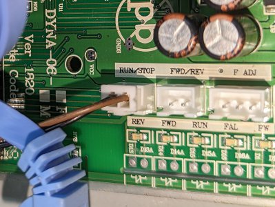
Question, about the forward and reverse? did you use the same connections the stock switch was connected to or did you use the fwd/rev pins.
Im sure the F ADJ can control the speed as well but how, I don't know much about this stuff.

PXL_20230326_041339784.jpg

I plan on using a LinuxCNC so I have a few other options possibly an arduino with 12-bit DAC or maybe a mosfet. I will have to look into this more.

Eric
 
Well, its ready to run. Almost everything is connected and operational. Still have to wire up the touch probe, I am still working on the spindle speed control, need to figure out something to do for chip management and mist coolant, but it is functional. I plan on running a dozen or so small parts then so that I have an hour or two on the ways and re tighten the gibs. not sure how often have to do that but I have been told it will probably wear in a bit at first then the wear will slow.


What is the runout on your (virgin) spindle?
I measured the spindle last night and I was only seeing about .00015 of runout, however after checking the inside of the spindle I pulled the gauge off the taper and noticed that the gauge wasn't moving as freely as it was before the test, So I will likely see about whats up with the indicator and recheck just to be sure I also checked the runout on a "not an actual" TTS tool holder with a tool in it and was only getting a total of about .0002 at the base of the tool directly at the chuck, so I like where this is going so far. Unfortunately, I do have an issue that needs to be addressed, the R8 TTS style collet does not set into the spindle far enough to let the tool holder to set up agents the spindle nose. I don't know if it is because it is not an actual Tormach r8 collet or if it is the spindle on the mill. I am gonna see if I can swing by Daves and try the collet in one of his mills and see if it sits all the way up where it should.


a few months back I tried contacting PM about it but they gave me a *******t reply about proprietary information blah blah blah.

From what I gather its a 0-12v signal which sucks because most analog outputs 0-10v. I see the acorn device has 0-10v analog ouput so one option is to use an operational amplifier (OP-AP) as a voltage buffer. The op-amp will take the 0-10V output from your device and amplify it to the 0-12V range required by the motor speed controller.

I think the stock controller supplies 12v out one wire through the potentiometer and back into the board on a different pin. that pin reads the voltage which tells the controller how fast the motor should spin. You would disconnect those wires and run a line from the acorns analog 0-10v output through the OP-AMP circuit and into the 12v input the pot was plugged into.

Question, about the forward and reverse? did you use the same connections the stock switch was connected to or did you use the fwd/rev pins.
Im sure the F ADJ can control the speed as well but how, I don't know much about this stuff.

View attachment 450330

I plan on using a LinuxCNC so I have a few other options possibly an arduino with 12-bit DAC or maybe a mosfet. I will have to look into this more.

Eric
I used the screw down connections that the factory FWD/REV switch was connected to. Acorn comes with a relay board that made connection real simple. All I did was run a wire from the the black/ground to the center input on one of the relays, jumped it to a second relay then ran a wire from each of the NO side of the two relays back to the other two screw connections on the spindle control.

As for documentation on the spindle control I got basically the same response from PM. I was hoping there was maybe something in the ribbon cable connector that would have been usable for a 0-10 VDC input but... I was digging thru the KB electronics web site and noticed that a couple of their signal isolator have a direct connection to speed controllers via ribbon cable, but I am not brave enough to just purchase and plug in (not for a while anyway maybe once I am committed to purchasing a real VFD and I can find one of those cheap enough I might experiment a little)... I will look around for a OP-AP and see what I can find, technically I should be able to hook into the factory pot connection and use the 0-10 vdc from acorn, I would just loose some speed in the top end... I mean, whats a few hundred RPM off the top, no big deal right. In the mean time I will probably cheap out and continue to use the factory pot to manually control spindle speed. I will just mount it to the case so that it doesn't continue to dangle in free space...

Ill get a few more pictures uploaded tonight when I have a chance.
 
On a side note. I did nave to get a little more in-depth on tramming the column on my mill. Turns out I had toad in some side shim to it as well as some front to back shim. May be something to keep in mind when checking over your mills.
 
Maybe I missed it, but what size stepper are you using for Z? I'm just looking to add a motor lift to eliminate the hand crank on my PM-932V (head and motor unit appears to be similar in size/wt to your PM-833), not full CNC.
Thanks
 
Maybe I missed it, but what size stepper are you using for Z? I'm just looking to add a motor lift to eliminate the hand crank on my PM-932V (head and motor unit appears to be similar in size/wt to your PM-833), not full CNC.
Thanks

Nema 34 1600Oz steppers on all three axis.

Sorry for the late reply. I honestly haven't done anything on here or my mill once summer rolled in here in Phoenix. I messed with it a little last week after putting in a room "stand it in the corner "style AC units, temps weren't too bad last week in the evenings, but then temps went back up this past weekend and that little AC couldn't really keep up. It also doesn't help the room is currently only half insulated even though it does not get any direct sunlight on the 2 walls that don't have insulation in them, 114 degrees is still 114 degrees. I had a couple out yesterday for a quick show and tell, the misses was trying to be convinced that the mill wasn't going to be too loud that she was going to be able to hear it in the house from the garage. He is cutting mostly nylon parts with the occasional aluminum, so it should be no issue for him. Any way after that I figured I should get on here and check the forum, maybe do a quick update.

I'll post more on here tonight but I am working on a couple of things over the next few days. some of it is shop/room upgrades some are on the mill.
 
Back
Top