ArizonaCNCKits PM833 conversion now avalible.

mike96

Registered
Registered
Joined
Aug 16, 2011
Messages
63
Had to edit to correct Dave's email address...

Gonna be a quick post this morning, just wanted to throw this out there. For those of us who have been waiting, it is now available. Dave from Arizona CNC Kits finished the conversion for the PM833 series mill. It is not on his web site as of right now however you can send him an e-mail at davedaxx1@yahoo.com and if he isn't flooded with too many emails already he should get back to you fairly quick. I am working on getting mine installed slowly as I am doing a few upgrades to the oiling system at the same time, that and the lake of time between work, school and all normal house responsibilities doesn't leave much time for play, however I will post up pictures as I go.

The kit does give an increase on a couple of the axis as for as overall movement, Z is limited to about 20" (sorry I don't remember the exact #off the top of my head) just do the the design of the mill column and slide, there is a bit of gain up at the top with the kit. If you want to remove the bracket at the bottom that retains the bearing for the original z motion gearing then you can gain additional travel at the bottom, however there may be a risk of the column flexing and the z getting a little sloppy without it. My understanding is this is a problem on some of the other PM mills (940 for example) that do not have the additional webbing in the z column that the 833 has. It has been a minute since the last time we measured X axis so I don't remember what the travel with the kit installed is, but as soon as I get it installed and moving I will post numbers here. Y gets a fair upgrade in movement, If you want to take the table from extreme to extreme you get just under 12" of travel and can get just a hair over if you clearance the bet a tad. That is with the table slide hanging out over the end of the bed almost over the motor.

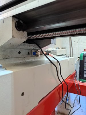
As for hardware, the Kit includes everything needed for the conversion. Z motor bolts directly to the top of the ball screw so there is no belt to worry about like with the heavy metal kit. With the way the z slide is cast it can be a bit tricky to get the ball screw in place but not horrible. Everything is double ball nut, X and Y are a 25mm ball screw and z will be available with either a 25mm or 32mm option. Yes a 32mm ball screw will fit, the slide needs to be flipped, more on that when I start posting on the install. But for now here are a couple of pick. Any picture with components installed are loose fit right now, I will add photos as things get finalized.

I will working on getting photos uploaded directly here later but for now... Here are clickable links to google.

https://photos.app.goo.gl/EsHm5yH5by8Wd9S48

https://photos.app.goo.gl/4eu1GHAc7BuPXXYNA

https://photos.app.goo.gl/u4Z9Z6AiWfVdVNUE8

https://photos.app.goo.gl/cy4spVLHFBSXPnLk7

https://photos.app.goo.gl/UdEzVUNKNgoxasWP9

Dave's video

Dave's video
 
Last edited:
Sorry for the delay. Between school and work I really only get 1 night a week to play with the toys and the weekends are usually full of honey due's. The last 2 weekends were filled with the addition of an Xtool D1Pro. So as you can guess I had other "special requests" to fulfill... Anyway back to the mill today.

Got most of the hardware done. Just need to pull the table off one more time after making the fine adjustments and aligning all the ball screw then she should be good to go. All I will need to do after that is finish up the electronics/electrical, mount the head and tram it in.

The kit is pretty straight forward nothing to out of the ordinary if you have watched videos on conversions of other machines this one will be pretty familiar. The biggest difference is that there is a large cast boss on the back of the Z slide as opposed to the removable mount that something like the PM30's/940's have. Dr D-Flo did the heavy metal kit install and that pretty much covers the basic install the biggest difference in Dave;s kit is the 32mm ball screw on the Z and the absence of the Z belt system. You will need to flip the Z slide upside down to use the 32mm screw but in my opinion worth it. It sets the ball nut under the casting so the weight of the head is supported by the casting sitting on top of the ball screw flange as oppose to the head being supported by three screws holding it up.

In D-Flo's vid, he says you need to remove the column to install the kit, this was the only way to remove the slide from the column. I originally tried to remove the slide with out doing this (granted I only spent about 5 minutes) but could not get the slide off the column. Then after placing the column back on and tightening the bolts down a tad, Dave came out to test fit parts and was like "look, you can pull the slide off without removing the column"... so try it before removing the column from the bed. If you don't have to take it loose and re-tram in your mill, Cool... But I will say installing the ball nut and adapter along with whatever you plan on using for an oil system should be easier with the column off the base... Just saying.

I also chose to do an upgrade to the oil system as you will see in the photos, for three reasons. 1, flipping the Z slide upside down puts the oil ports on the slide at the bottom of the ways, and as you know gravity pulls things down. I prefer the oil going in at the top of the ways so that gravity can do its job correctly. 2, I did not like the way the oil lined were just basically set into the holes that were drilled into the casting, it makes for a mess on the inside of the machine when half the oil ends up on the top of the saddle or running down the inside of the casting because the oil oozes out from between the oil line and the hole it is shoved into. And 3, I wanted to take full advantage of the one shot oilier by incorporating the ball screws into it. As you can see in the pics my oil block sits in just the right spot to access the adjustment screws thru the large hole left in the side of the column where the Z height adjustment was.

Dave sends the ball screws out with a M6x1.0 grease fitting installed and I did have to flip it over to replace it with a compression fitting. I did clearance the corner of the mount a tad for that fitting as you can see in the pic. It looks like the fitting is forced agents the mount but it didn't take much to get clearance so I don't believe there was any pressure agents the fitting, it was just touching lightly.

Also I did cut the lower bearing mount to clear my oil block. The bearing mount is not needed to hold a bearing but I am leaving it in place as I believe it does help with some rigidity of the column at the lower part of the way opening. Not sure how much redgitity it adds but better than nothing I am sure.

Now lets see if I can get pics from Google Photos to attach......
...
..
.
Guess not the forum doesn't like the http"S" part of the link apparently. While I wait for my pictures to download and resize a tad...
20230417_155101.jpg


20230417_155107.jpg


20230428_205726.jpg


20230428_205738.jpg


20230428_210430.jpg


20230428_210457.jpg


20230428_210049.jpg


20230428_210727.jpg


20230428_210800.jpg


20230428_212127.jpg


20230428_213543.jpg


20230428_213556.jpg


20230428_220747.jpg


20230428_210908.jpg


20230513_164334.jpg


20230513_164407.jpg


20230513_203436.jpg


20230513_203440.jpg


20230513_164521.jpg


20230513_205809.jpg
 
Thank you for posting this.
This is the exact conversion I am contemplating. I am interested to hear how well everything works for you.
 
I'll post as things get finished. Between work, school and adulting I dont have much time to work on getting this finished. As of right now I have the mill about 2/3 - 3/4 of the hardware done. the table is now fully reassymbled, I just need to fine adjust the gibs and take a couple of checks to make sure the ball screws are aligned. The Z slide is basicly done all I need to do is tighten up one of the lines for the oil system. After that I can reassymble the head and bolt it back on the slide, start connecting the electronics and make everything move under power, then I can tram the column in, it will be done and I can start making chips.
 
Are you going to put an air spring on the Z-axis?
??? Like something to help with the z head going up? If that is what you are talking about, I considered doing a counter weight to assist Z and take some of the load off the stepper, but I havent made a solid decision on whether or not I will. I dont have enough room between the mill and the wall the way it is set up right now. I woild have to pull the mil off the wall a tad and where it is right now there is not a lot of room around it. Plus the room it is in right now is temporary, the mill will have to be moved eventually when that room gets torn down and the carport is converted to a garage.
 
??? Like something to help with the z head going up? If that is what you are talking about, I considered doing a counter weight to assist Z and take some of the load off the stepper, but I havent made a solid decision on whether or not I will. I dont have enough room between the mill and the wall the way it is set up right now. I woild have to pull the mil off the wall a tad and where it is right now there is not a lot of room around it. Plus the room it is in right now is temporary, the mill will have to be moved eventually when that room gets torn down and the carport is converted to a garage.
Yes. I have seen people install 160lb gas springs (like those on a car trunk or hood) to take some of the load off of the Z-axis screw, and speed up it’s motion.
 
Ok, your talking air spring. Something to look into I suppose. I have sen a few mills don this way bit not sure if this is the way I want to go.
 
Update.

So it is about 98% done. I have all the steppers mounted, all the limit/home switches installed and I spent a couple of nights running the axis around calibrating the motion to a pretty darn good less than .0005 in accurate over 6 inches of movement. I am tossing the idea of making a couple of test bars to see if I can dial the accuracy in just a bit more but we will see, little bits at a time. Right now I am waiting on a machinist square so that I can make sure the Z is vertical to the bed inline with the y axis. I could probably use an indicator across the table... Maybe later tonight. I needed a couple of squares anyway...

The limit switch mounts aren't going to win any beauty pageants but will function. they are on the list of things to remake later on once everything is set up and fully functional, right after the belt grinder, new electronics cabinet, indicator holders, cover plates for open holes on the mill... etc. etc. As I told someone else once before, its all tempermanent.

You will see in the photos this kit gains quite a bit of Z height if you don't mind overrunning the ways a bit. same can be done with Y but I don't have any pictures of Y in its full extension... However I am having a bit of a problem with extending Y out to its max extension. I have found that once it is all the way out I cannot pull that axis back in using a rapid movement. I don't know if it has something to do with the steppers I am using, the fact that I may not have something adjusted correctly or if it is the gib/table twisting slightly. whatever the cause once the table is that far out and I command it back in anything faster than about 40-50 IPM, my steppers stall out completely and the table stops moving until they slow down at the end of their movement, then the tale gets a small jerk and will move as it should. So in the mean time I am going to leave the mill set up to only have about 10" of travel in Y. I don't feel I need the 12" that this kit can allow for at this time.

As for X I am going to be OK with letting the table stop motion so that the ends of the table are even with the ends of the saddle. Mostly because with all the extra oil block and lined on the left side it limits how far into the saddle the table can travel. the stepper coupler will hit the lines if I go in to far. so to keep things even that is where I stop for now. If not for that then the table will cross over the ends of the saddle about an inch to an inch and a half IIRC before the stepper mount bottoms on the saddle.

Other than that I have spent a couple of days adjusting acorn and mounting mill head. It is all up and running, I could cut a few parts now but am restraining myself until I have a chance to make sure the head is straight and true. I am trying not to rush things. I also need to make a tray for the underside of the mill and do some adjustments to the oil system. apparently I am over oiling the ball screws.


20230528_214312.jpg

20230528_214335.jpg

20230529_115424.jpg

20230529_115442.jpg

20230529_115445.jpg


20230529_085017.jpg

20230529_115455.jpg
 

Attachments

  • 20230529_115445.jpg
    20230529_115445.jpg
    224.9 KB · Views: 43
Did you have to take the column off of the base to install the Z ball screw?
By any chance did you weigh the head when it was off?
 
Back
Top