Anyone Have A Toolmaster Mt ?

shott8283

Registered
Registered
Joined
Dec 10, 2012
Messages
51
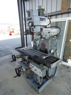
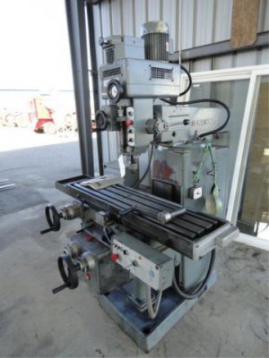
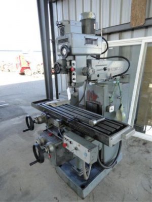
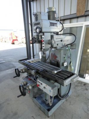
Picked up a nice 1973 Toolmaster MT with power feed on the X axis. Everything seems to work on the machine other than the power feed. Looking for some assistance understanding some wiring.

Starts with a FEMALE cord end (120V) wired into a junction box (factory) on the L side of the machine. from that box goes to the motor for the power feed thats attached to the gear box.


I havnt plugged the cord end into anything b.c I don't have a double male cord to plug into , and I don't want to fry the motor or contractors by sending the wrong voltage into it.

Wondering if anything has a smilier machine that give me some insight to the voltage requirements for the power feed motor. The plate on it is unreadable.
 
There should be some plate on the motor of the feed motor? pictures of the plug and motor may help? Is the mill 3 phase powered.? The power feed motor on your mill may be 3 phase too but I dought it . Do you have any way to ck the output on the box it plugs into. They have cheap plug in models that will do it for you .How many wires coming from motor on feed? if three I think it would be 110 volt . Does the feed have a limit switch on machine? Hard to tell without seeing . But like you said two male plug needed to power it is not right by any I've seen.
 
Last edited:
I did some digging around, Ill get some pics up later today. I believe the cord end is the feed for the coolant tank pump. Im not 100% sure about that yet but it makes the most amount of sense.

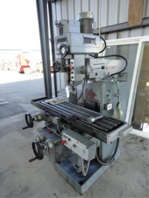
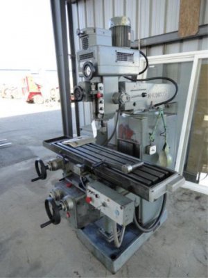
This is a photo of the mill (not mine but same exact model)

7667302_3DR0OAVKP.jpg


It doesnt have the traditional style of power feed seen on bridgeys .. its a fairly stout motor under the table bolted to a gearbox with an elaborate trip dog and rapid circuit involved. I have to finalize my RPC before I can continue trouble shooting. Just got the mill home this week.

I have to clean up the plate a little bit to try and read it but its pretty illegible. its a stamped plate so I might try the pencil shading trick on a piece of paper to discern any info that may still be left.

7667302_3DR0OAVKP.jpg

7667302_3DR0OAVKP.jpg

7667302_3DR0OAVKP.jpg

7667302_3DR0OAVKP.jpg

7667302_3DR0OAVKP.jpg
 
By the way it looks the motor is powered the same as the mill. Your contactor may be at fault or sometimes it only needs the wires reversed on the feed , seems another one on here or youtube . That's it a YouTube guy with an alzmetal drill press thought it was bad and only needed a wire change , I'll try to find it be back and let ya know .Look up James Kilroy , alzmetal drill press videos. I'm sure he had a very simuler problem on it.
 
Last edited:
Hi shott,

Congrats on getting the "new" mill!

Sorry I do not know that mill, however two things:

1) Personally I would avoid a male-to-male cord in my shop. It just sounds too dangerous!
I agree that the female connector you see is likely an output to feed the pump, not an input to the feed motor.

2) Is it possible that the table has limit switches to stop the feed at the end of travel?
Perhaps the table is at one end holding a switch open, or you might even have a bad limit switch.
You might try moving the table to the middle (away from all stops) manually, and then try the power feed again.

Please post back with any progress or more questions.

Good luck and be safe!
-brino
 
thanks for the replies fellas. this is what i have been able to figure out so far

with some basic circuit tracing and shooting some wires... that female cord end is in fact the power feed for the coolant pump that is on a separate cart. that is operated from a 3ph transformer down to 110 which explains the cord end

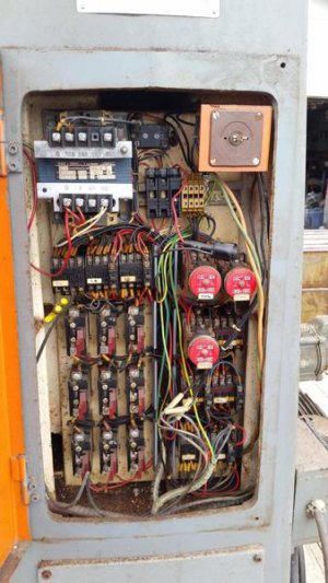
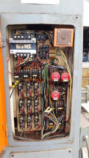
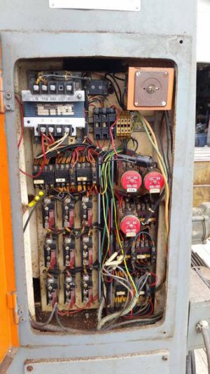
the table does have trip dogs on it. while they are currently not activated (or tripped, the table is dead center right now) I can not by hand depress the plungers. leaves me to believe there is something going on in the control box. its going to take some work to get into it since i don't believe its ever been serviced and the fasteners are being stubborn as all hell.

all this would be WAY simpler if the machines were in my shop and powered up, but I have yet to get my hands on fork equipment to offload them and my RPC is in the mail..

being patient is the hardest part when getting new toys!
 
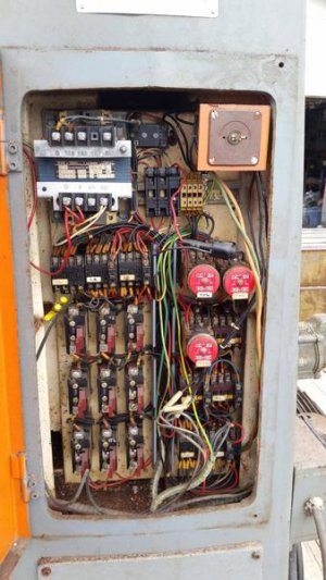
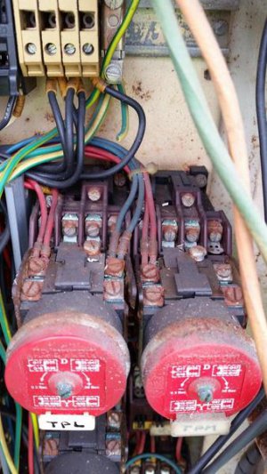
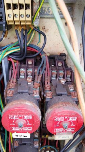
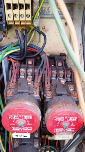
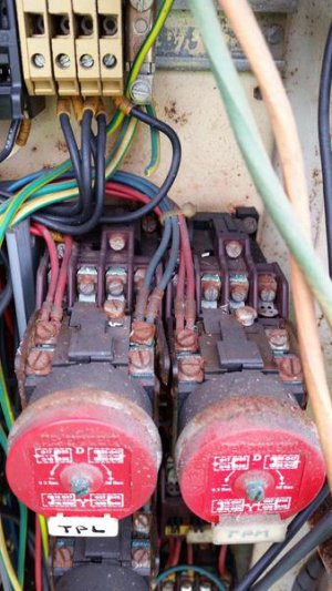
this is a little taste of the fun i have been having BTW

REALLY wish i would have stayed in EE school.. math kicked me out

mN3gtYb.jpg

4RMgkeU.jpg

mN3gtYb.jpg

4RMgkeU.jpg

mN3gtYb.jpg

4RMgkeU.jpg

mN3gtYb.jpg

4RMgkeU.jpg

mN3gtYb.jpg

4RMgkeU.jpg

mN3gtYb.jpg

4RMgkeU.jpg
 
ouch, there are some seriously corroded connections in there!

with the wire tags almost unreadable, I'd suggest removing a screw and its associated wire one at a time, then getting a little dremel wire-wheel in there to clean it, cut, strip and reconnect it and then move to the next. definitely not a pleasant task, likely one that needs done to get the thing running consistently.

Remember that in the end it WILL be worth it!

-brino
 
for what i paid for the mill and what it would go for on a fair-market value, every single second i put into the thing to get it into tip top shape is worth it. think ill have a clearer picture of things once its fired up and i can shoot out what it and isn't getting voltage
 
Back
Top