A Possibly Very Short Restoration Thread

Yes, you are missing the lower bracket. The saddle has those threaded holes, there should be a bold on bracket to hold it to the ways.

Sent from my SM-T500 using Tapatalk
Oh, I have the bottom bracket, but i took it off when i took the saddle off to clean it, and left it off briefly to take that picture. It looks as though there should be a 1/8" gib in that thin space between that screw on the right and the back of the ways.
 
I am not sure if I understand, but I think the front and back location and alignment of the saddle is defined by the V ways. That piece in the back only stops the rear of the saddle from lifting up.
 
I guess the flat-tip set screw with the lock nut on it at the back of the saddle is for an option my lathe doesn't have? There is an adjacent hole that also bears on that empty space, into which the set screw will also fit. This was why I thought there might be something that belongs up in there. I couldn't see the screws dragging on the back of the ways, and couldn't figure why else they were there.
 
I put a dial indicator on various parts to see what kind of flex and run out I have. Concentricity of the spindle is less than a thou, but it does move. I don't have a half-thou gauge yet, so I don't know how much it is. I put a shovel handle thru the spindle and pushed down and zeroed the dial, then let go, and it didn't move more than a thou, and a little bit again when I tried picking the lathe up with it.

I cranked the carriage all the way to the tail with the threading dial off, set the carriage lock, then just let off it a bit. I put the gauge mount on the flat way and the indicator on the flat of the cross feed and tried picking the carriage up at various points along the bed. At the tail I couldn't get more than a couple thousands, but it increased as I went along the bed. At its worst, in almost the exact middle of the bed, it was 50-60 thousands, and went down to 20-30 right at and just in front of the headstock.

Time will tell if this is significant enough to keep me from what I need to do (learn, mostly), but it was pretty shocking to put a number to it.
 
Last edited:
I watched a video on evaluating a lathe bed and realized I did the carriage bit wrong. Apparently I'm supposed to put the carriage at the headstock, set the carriage lock and then back off just slightly, and then try to crank as far as it will let me, to determine where (and how much) the wear is. I'll do that in the morning, but with the ridge on that front V, it's enough.
 
Well, I had a whole lot written in here, but then the page decided to refresh and I lost it all. Not sure I care enough to rewrite all my prose, so here's the gist:

* I ran the above test, running the carriage to the head and setting the carriage lock, then cranking it toward the tail until it gets tight. I made it a little more than halfway, then had to loosen it several times to get it to go the rest of the way, getting a half-crank or so for each 1/8th-turn I loosened the clamp. Wound up almost a full turn out from the halfway mark.

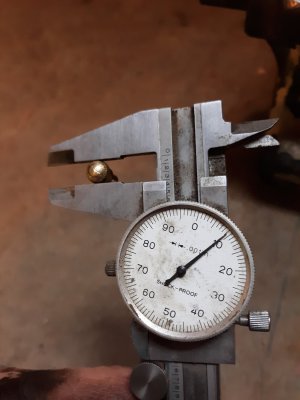
* I put an indicator mag base on the cross feed, with the zeroed indicator on the peak of the front way, and ran the carriage from tail to head. +0.018-0.022 on several runs. Also got +0.014 when compared to the tailstock flat way, and +0.009 when compared to the unmilled flat between the rear inverted vee ways.

* Tested the new used VFD, it will power up on split phase 240, so I can use the 3-phase motor.

* The motor ohms and megs good, but has a few cracked wires, so I pulled it and opened the case. Found metal shavings in the windings- Tubal Cain is right, compressed air BAD. Cleaned all that out in prep for rewiring the core. Never found shavings anywhere else in the machine.

* Ordered some 1-7/8"x8 nuts to make a faceplate/chuck, and an original toolpost and set of Armstrong cutting tool holders, along with some bits. Once I make a chuck, I can do a test bar.

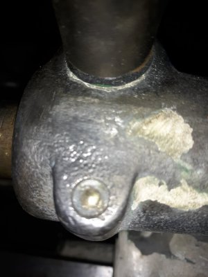
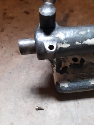
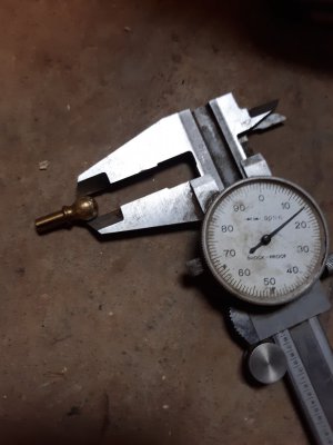
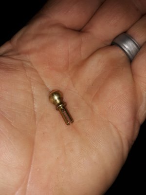
* Learned about the original daubers these came with, so went looking for mine. Under the paint was a bronze blob- looked like someone brazed the hole shut? Dug more paint out, no, that's brass, maybe someone broke it off in the hole? Heated it up with a heat gun until it wiggled and turned a bit, then inverted the tailstock and tapped it with a rubber mallet. PING, out fell a dauber, but the head is 0.005" smaller than the original hole, so I don't know what this goes to.

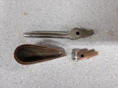
* The original tumbler trigger was broken, and my attempt to solder it failed, so I cut a new one out of a scrap of stainless at work. Not as pretty, but works great.

Next up- rewire and reinstall the motor, wire up the VFD, and make a chuck and a test bar when the stuff gets here. Oh! Almost forgot- also got a new (er) 10R spindle and bearing caps to replace the scratched ones, I'll scrape the headstock a bit and polish it before installing them. Also have to get new felts.
 

Attachments

  • 20240112_170408.jpg
    20240112_170408.jpg
    371.1 KB · Views: 3
  • 20240113_154810.jpg
    20240113_154810.jpg
    177.3 KB · Views: 4
  • 20240113_161232.jpg
    20240113_161232.jpg
    182.8 KB · Views: 4
  • 20240113_161336.jpg
    20240113_161336.jpg
    169.2 KB · Views: 3
  • 20240113_161357.jpg
    20240113_161357.jpg
    164.8 KB · Views: 3
Last edited:
Since this dauber is too small for my toolpost, I figured I'd offer it up here. The ball is 0.309", the diameter of the split shank below the collar is 0.187", OAL is 0.750". There are some scratches in the top of the ball where someone must have tried to pry it out. If anyone can use this thing, I'll send it to you gratis, just drop it in an envelope. First PM with an address can have it.
 

Attachments

  • 20240114_170741.jpg
    20240114_170741.jpg
    176.8 KB · Views: 3
Back
Top