A few questions about my new to me South Bend 13"

Second is to tap that hole for whatever size set screw that would fit and file a flat on the shaft. Either would work just fine, they only differ in the tools needed.
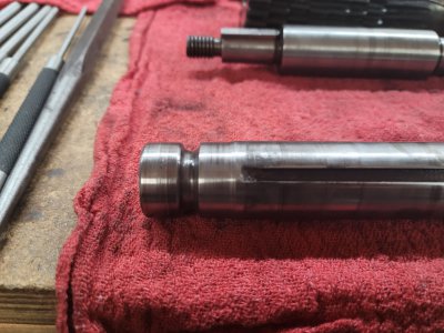
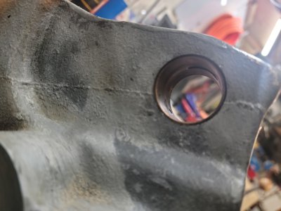
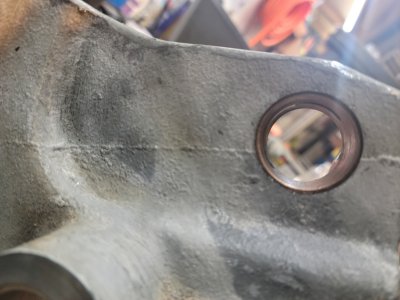
I like this idea. I will probably go this route once I get done working through the rest of the machine and am ready for final assembly. I really don't like the excess play and the shaft sliding back and forth. I know eventually it will end up driving my nuts and I'll end up fixing it anyway.

Working on the gearbox now and already seeing some tell-tale signs of crude attempts of dismantle. Pry bar marks on the faces of the external gears and remnants of a destroyed tension pin replaced with a much shorter dowel pin. The promising thing is, that appears to be as far as they got as the taper pins on the gear shafts looked factory like they had never been driven out and the brass bearings look to be in good shape. Oh and plenty of oil all over everything.
 
Or measure and make a brass spacer bushing to fit the gap for now.

Or whatever you have handy.

You can drill existing hole to fit the pin.

It will take the play out and is quick DU-FUR fix.

Du for now...

Sent from my SM-G781V using Tapatalk
 
Well looks like I spoke a bit too soon on the gear box. You can pretty clearly see they ran it dry for some amount of time anyway. Not real worried about any of it except the tumbler shaft. You can see from the pictures the left side of the shaft has been significantly worn. I measure it at 0.97" or 0.030" under the 1" of the rest of the shaft. Lots of play in the bearing. You can see the wear in the bearing as well.

The other shafts don't seem to have much play in them but you can see and feel some minor score marks from lack of lubrication. I'm not sure what amount of play is acceptable on these, any advice?

I don't know that I have much option on the tumbler shaft other than to just get a new bearing to minimize the play as much as possible, slap it back together, keep it good and lubed and hope for the best. Certainly open to opinions or suggestions if anybody has any.

Cheers,
Brent
 

Attachments

  • Reduced_20221004_235856.jpg
    Reduced_20221004_235856.jpg
    370.9 KB · Views: 16
  • Reduced_20221005_000018.jpg
    Reduced_20221005_000018.jpg
    261.3 KB · Views: 16
  • Reduced_20221005_000051.jpg
    Reduced_20221005_000051.jpg
    264.5 KB · Views: 16
2 or more options.

One, use existing shaft, remove material to make a straight and known size.

Get larger stock, bore to fit above, place on shaft then turn to final size, sleeve the shaft back to original.

Replace bushing in gearbox.

Two, locate replacement shaft and bushing.

Three, make replacement shaft and bushing.

You have a lathe, it makes round things...these are round things...

Sent from my SM-G781V using Tapatalk
 
My wife: "What will you make with a lathe?"

Me: "Lathe parts"

Rick "reading this thread with interest" Denney
 
Well it took a while, but finally finished up the lathe restore.

This is what I ended up doing to fix the tumbler shaft. I used my small Grizzly lathe to clean up the worn end of the shaft, then created basically a press on bushing from a pipe I had laying around in the garage using my small Precision Mathews Mill and a boring bar head. Pressed the bushing onto the end of the shaft, with my 20 ton press, then turned it down to the proper diameter on the small lathe. I got lucky since this shaft was pretty much the absolute maximum length of stock my small lathe could fit. It honestly turned out much better than I anticipated. I thought for sure I would end up destroying the shaft, since I don't have a ton of faith in my small lathe. It works fine for getting stuff close, but I've never been able to get the precision and finish out of it I would like. This however turned out very good for my skill level anyway.
 

Attachments

  • Reduced_20230504_020717.jpg
    Reduced_20230504_020717.jpg
    467.6 KB · Views: 8
  • Reduced_20230504_020705.jpg
    Reduced_20230504_020705.jpg
    340 KB · Views: 8
  • Reduced_20230503_225214.jpg
    Reduced_20230503_225214.jpg
    349.6 KB · Views: 8
  • Reduced_20230503_223644.jpg
    Reduced_20230503_223644.jpg
    317.2 KB · Views: 8
  • Reduced_20230503_223635.jpg
    Reduced_20230503_223635.jpg
    512.5 KB · Views: 8
This is the finished product. Still need to get placed in it's final spot and leveled though.

I did want to get some opinions on the rpm and how it runs. I used a tachometer (just cheap harbor freight one) and took measurements on the three direct drive speeds. What I ended up with is 200/405/740. Now according to the South Bend spec sheet I obtained it should be 270/497/940. Does this seem okay? I'm sure the rpm will vary some between specific machines. Would you guys say I'm good to go with trying to use this or should I look a bit more into the motor and VFD setup this came with?

Also the potentiometer to control the VFD seems to be a bit weird. I have to turn it about half way before it really started to vary the speed any from just barely turning. Then I only have a bit left to control speed from there on. I was just testing with the tachometer running at 100%.

Just looking for some opinions and guidance as I have zero experience with VFD's and such.

Cheers,
Brent
 

Attachments

  • Reduced_20230716_143135.jpg
    Reduced_20230716_143135.jpg
    457.4 KB · Views: 5
  • Reduced_20230716_143223.jpg
    Reduced_20230716_143223.jpg
    320 KB · Views: 5
  • Reduced_20230716_143254.jpg
    Reduced_20230716_143254.jpg
    416.5 KB · Views: 5
Just imagine that machinists were able to produce acceptable work before VFDs were invented --- small differences in RPMs really do not matter.
 
For one thing the pot seems to be the first problem to address.
You might be able to clean it but more than likely it will need replacement.
The voltage that is varied through this component is what controls motor speed.
 
Back
Top