8 day clock

A little more detail on making the burnisher might be good. I know what you mean on making one, but not really sure of what grit belt you need to use, or whether there would be any need to make two, one a little rougher than the other. What angle do you present the tool to the belt?

Maybe a picture or two?
 
OK Tony detail as requested.
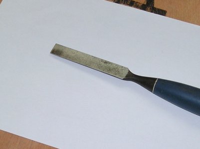
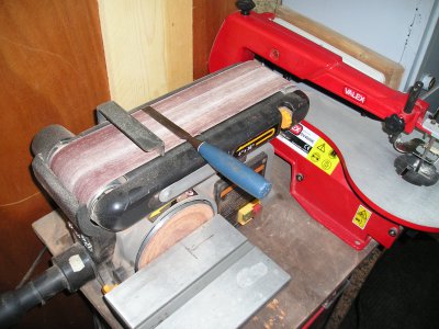
The burnisher can be made from any good steel that will hold an edge, the old wood chisel works fine, and having a handle is nice to use.
the blade is presented 90° to the belt .the belt is 120 grit. No point in trying to make a finer one.
the tool is used with firm pressure and a little spit for lubrication. On fine pivots a wooden block is necessary under the pivot to stop it from bending. it can take time to produce the high polish necessary for a good bearing.

I have been told that a burnisher that has been rusty and cleaned with rust remover works very well but i cannot confirm this.


Thanks for asking for more detail I need the feed back.
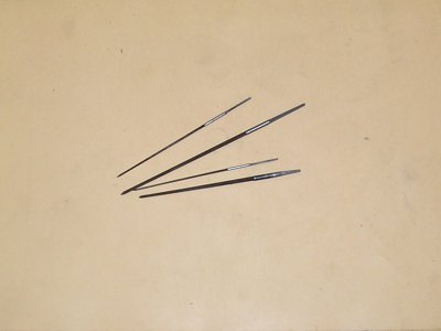
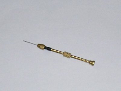
Photos of broaches - Drill - And burnisher attached


BRIAN

P1011251.JPG P1011276.JPG P1011278.JPG P1011279.JPG
 
Last edited by a moderator:
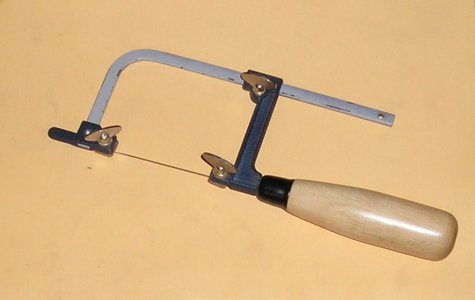
I forgot the piercing saw, you cant do without this bit of kit, A fret saw will work but its clumsy so you break more blades.

The blades I use are 12x32x0.18 very fine. and 12x23x 0.24 fine I find if i use coarser blades they tend to jam so although the finer blades are more delicat I don't break so many

For those of you without a mill this is the tool for fretting out the frames and wheels.

P1011274.JPG
 
Last edited by a moderator:
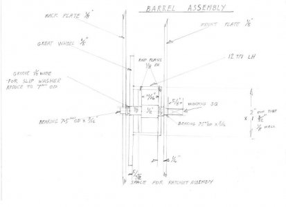
Another drawing this time the barrel assy.

You will find certain dimensions are missing.
1/ the overall length of the shaft has to be longer than shown to allow for centres but as this depends on your machine --drive dogs--etc its up to you to make the allowance necessary.

2/ OD of barrel end plates?? tubes are hard to get with exactly the wall thickness you want so you may have to make a (best fit)

3/ Arbor length between the plates (on the job measurement)

4/ Slip washer position also OGM

all these points will be covered in the text.

BRIAN

img095.jpg
 
Last edited by a moderator:
More drawings salvaged from my pile of notes.

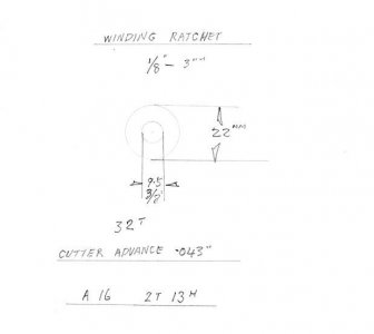
The ratchet is just the blank size, the tooth depth is a on the job measurement (By now you must be fed up with me saying this but clockmaking is a ART)

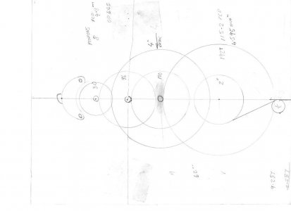
The gear lay out is the first drawing I made of the clock in the early stage of development.

img097.jpg img098.jpg
 
Last edited by a moderator:
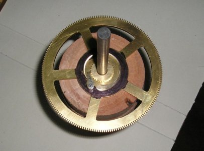
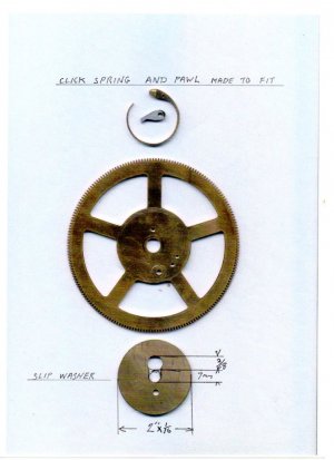
More on the ratchet assembly and the Slip washer.

The slip washer holds the assembly together, its position is marked on the shaft and the groove cut after you are sure all is OK with the ratchet assembly inside the barrel.

BRIAN.

P1010962.JPG img099.jpg P1010966.JPG
 
Last edited by a moderator:
Now we come to the part that turns most newcomers away from clock building I hope I can make this as painless as possible.

Firstly a list of the divisions required.

192 Great wheel

100 Centre wheel

96 3rd & hour wheels

52 Minute wheels

32 ratchet

30 scape

8 pinions


Those of you with dividing heads will not find this hard although you may find the plates for 192 and 52 are not in your set but it is easy to make these .

Dividing can be done directly by having a disc with the correct number of holes to match the gear
A well known clock maker used old band saw blades ,cut off the required number of teeth, measure the length , make a wooden disc the correct diameter, and fit the blade around it???? I have heard of old 8mm film being used in the same way??

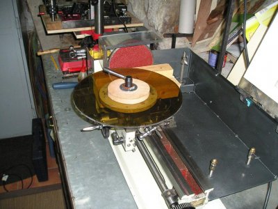
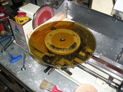
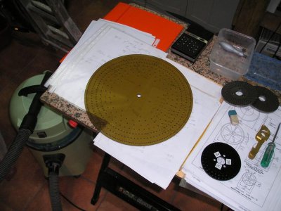
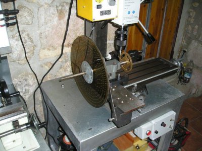
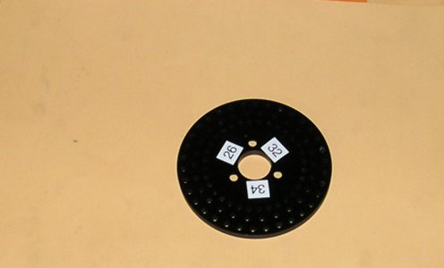
So I thought this is not the best intro to clock making so I have made a Master Disk, it has all the divisions required to make this clock and it will be available on loan when you are ready to cut your gears.

It is made of perspex ( the only material i have available ) so will require using with care, But the advantage is its light to post.

If you need help fitting tis to your lathe or mill I am shure you are in the right place to get it.

BRIAN
P1011275.JPG P1011280g.JPG P1011281.JPG P1011284.JPG P1011282g.JPG P1011285.JPG P1011287.JPG
 
Last edited by a moderator:
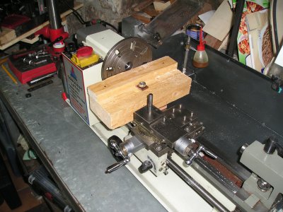
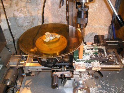
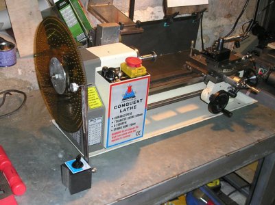
This is a mock up of the dividing plate fitted to the mill. in real life the gear blank will require more support.

the bearing could be something like a motorcycle wheel hub. Food for thought.

BRIAN

P1011289.JPG
 
Hello Brian,
I'm a new member will be retiring soon work 3 day week as a toolmaker, have been looking for a clock to make and came across your 8 day clock. Perfect for what I want . At the moment I have a 9" southbend lathe that I'm reconditioned about ready to go back togeather also a drill mill a 8" rotary table with tailstock and take delivery of a 7" x 14" mini lathe this week. I've downloaded your "Beginners Clock" also your extra drawings have yet to read.
Will be some time off before I make a start but will start getting materials etc.
Thanks a lot for supplying all the information it is a great help as I have been looking for something like this for sometime.
 
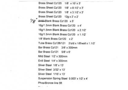
Hi all and welcome to ifredaj , thanks for joging my memory re a materials list so I have posted the list
that I made when I started the project, anything else came out of the scrap box.


For your information Tony Wells is revamping the sketches into readable drawings so dont dispair at my ineptitude in this skill.

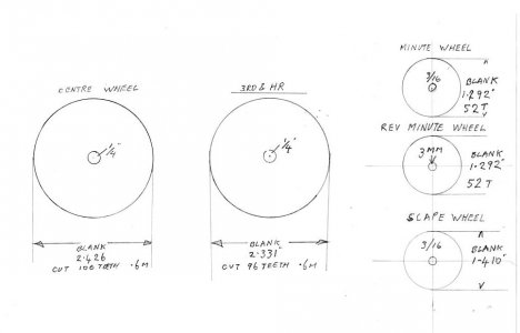
I have added the drawing of the gear blanks for the gears that I used from the beginers clock by Eliot Isaacs .
In the original the dimensions are either confusing or incorect.

In the text he states that the minute wheels can be cut together, and the drawing only shows the wheel with a 3/16 hole, but the reverse minute wheel requires a hole of 3mm because the pinion is fitted direcly to the wheel.

For those with limited dividing facilitys he recomends cutting the minute wheels with 50 teeth because this number is easyer to divide this gives a fractionaly narower tooth but will not cause trouble.
On my drawing I have given the correct no of teeth 52 I had to make a new plate for my dividing head to get this.
img105.jpg img106.jpg
 

Attachments

  • img104.jpg
    img104.jpg
    23.4 KB · Views: 79
Last edited by a moderator:
Back
Top