32x40 H -- Gas Engine

I decided to continue with the flywheels so I can ensure that all is OK before screw cutting the main shaft.

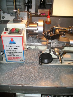
The first problem was to get the 5" diameter blank onto the lathe. no way will any of my chucks take that diameter???

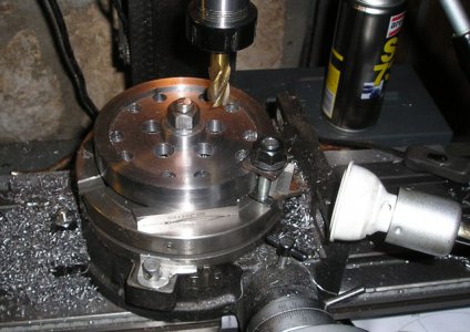
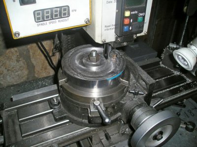
So we drill a hole in the centre and mount it on the rotary table and mill a recess that will fit on the little 4 jaw with the outside jaws locating on the inner edge.
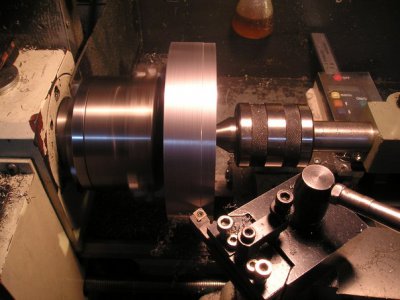
P1012947.JPG

P1012949.JPG

Yep Now we are really making Chips.

P1012950.JPG


Brian.

P1012947.JPG P1012949.JPG P1012950.JPG
 
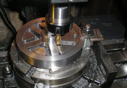
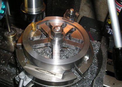
Now it's on to the rotary table to Mill out the spokes . first dill out the corner holes then it's a game of join the dots.

P1012955.JPG

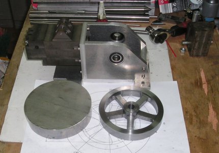
After reducing the 2.7 kg blank to a mere .77 kg we have a fly wheel,

P1012956.JPG


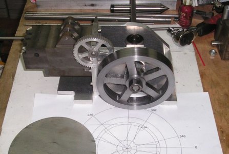
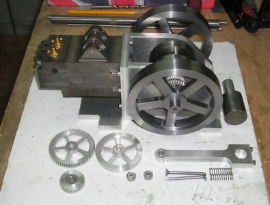
Then a quick shuffle of the parts to get a quick idea what it may look like?

P1012958.JPG


Now I need another for the other side.


Plod, Plod,

Brian.

P1012955.JPG P1012956.JPG P1012958.JPG
 
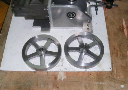
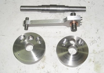
Pushing on, the second flywheel is finished as I did not include any photos of the "Join the dots" milling operation I took a couple this time.

P1012960.JPG


P1012961.JPG

Now we have two.

P1012962.JPG

P1012963.JPG


Brian.

P1012960.JPG P1012961.JPG P1012962.JPG P1012963.JPG
 
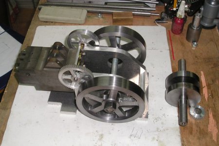
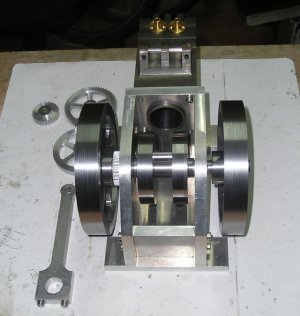
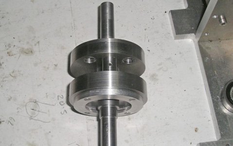
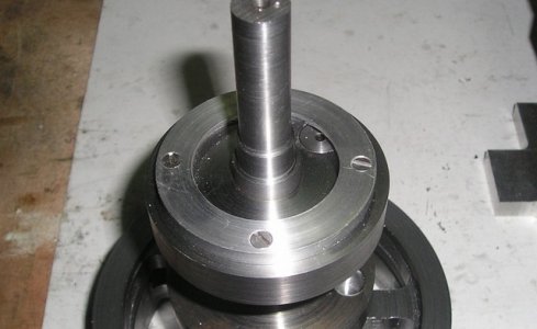
Just could not resist putting the crank in to see how it all fits.

The pile of parts as it now stands.

P1012964.JPG

P1012965.JPG

Brian.

P1012964.JPG P1012965.JPG
 
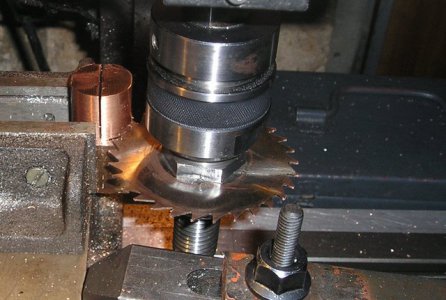
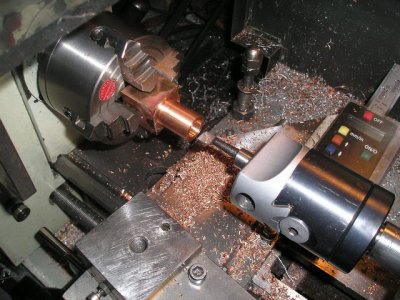
I have made a start on the Big end bearing, After taking the corners off the piece of bronze I split it in half with the slitting saw.

P1012966.JPG

Then soldered the parts back together

P1012968.JPG

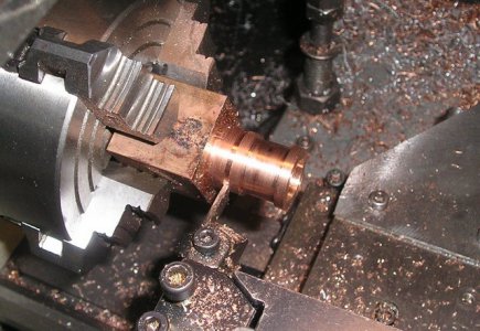
Turned the out side to the largest diameter (the flange) then bored the inside to the bearing diameter.


P1012969.JPG

That's it for today.

Brian.

P1012966.JPG P1012968.JPG P1012969.JPG
 
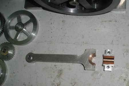
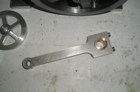
The problem now was to turn surface that mates with the connecting rod, this has to be a really good fit in the rod so it will not turn, a small locating pin will be fitted but the bearing must not rely on it ,
This has the added problem that when it is to size, I have to unsolder and clean up the joint so some small allowance must be made.

P1012970.JPG

P1012973.JPG

P1012972.JPG

Ready for final fitting to the crank.


Brian.

P1012970.JPG P1012973.JPG P1012972.JPG
 
The oil feed for the big end on this engine Is going to be a little different , I doubt if the idea is new but it's new to me.

A drip feed oiler will supply oil to the outer side of the crank web where centrifugal force will spin it into the collecting ring and the pass it into the big end.

P1012974.JPG


P1012975.JPG


Hopefully this will give better lube than the usual big end oil cup without having to stop the engine and be less messy than splash feed.

We will see.

Brian

P1012974.JPG P1012975.JPG
 
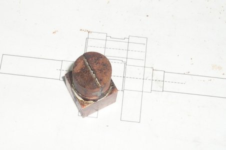
The fiddly jobs today, Fitting the pins to the con rod bearings and balancing the crank.

Only the threads to retain the fly wheels and the key way's on the main shaft to do and the crank can be assembled,
Boy will that be a relief.

P1012976.JPG

Brian.

P1012976.JPG
 
Did you just static balance the crank? I cant see any dimples in it, It must have been close.

Cheers Phil
 
Hi Phil
The crank / rod assy was balanced between centres statically and the oval areas milled out to get it right.
I did not make through holes as I want a clean look on the outside of the webs. And I did not want to interfere with the oil collector ring.
Brian.
 
Back
Top