2017 POTD Thread Archive

Had a good day today despite the appalling humidity.
Finished re building the franken burner after its previous demise from fire.
So it had to be used.
I have been revisiting the altitude slo-mo controls for the scope and had to mill a key way into the altitude shaft, this meant it also needed a new tabbed washer to fit.
No worries now the eroder is working. I placed all the electronics inside the welder case so there was only a three core cable running to the eroder head.
View attachment 143681
Fully submerged in a bath of kerosene and a metal tank this time, no plastic stuff.
A small aquarium pump delivers a jet of fluid to wash debris from under the electrode.

Here is the shape that is being burnt through the 0.9mm sheet of stainless.
View attachment 143682

and here is the electrode burning out of the kerosene bath. Quite a powerful arc.
View attachment 143683

A quick check half way through, approx 40 mins.
View attachment 143684

Almost through, 1 hour and 20 mins total so far.
View attachment 143685

Finished. Just under two hours to get this far. Now it just needs a tiny bit of cleaning to fit.
View attachment 143686

I milled a key way in a 12mm bolt so I could clean up the edge.
View attachment 143687

and it fit nicely and snug with no perceptible backlash but slips along the shaft without sticking.
View attachment 143688

Total time from start to finish allowing 20 mins cool down each time the coil reached 80'C was 4 hours 15 mins.

There Is obviously a story behind this Frankenburner, curiosity had got the better of me?
 
In the course of the original build I blew 1 bridge rectifier, 4 capacitors, 2 wire wound resisters and 3 diodes before I got it working.
I just used salvaged parts from some old boards
Second time I used it I shorted it all out to earth somehow.
I re wound the coil with more windings of finer wire to get the resistance and milli-henrys closer to the diagram values whereupon it could run for longer before the heat became too much.
Then a couple of months ago I tried to run it by just trickling some kero as a dielectric and of course it hit flash point and caught fire and burned out all the caps as they were sitting in the flames.
http://www.hobby-machinist.com/threads/goofs-blunders-you-should-avoid.49036/page-10 message 272
Its actually been a great little machine and very handy, particularly burning out the heaps of broken taps my clumsiness produces.
Now the coil goes from ambient (33'C today) to 80'c in about 20 mins, I have run it up to 98'c but started worrying about a burnt coil so stop at 80 now.
This build has all new electronics but the rest is what I had laying around hence the wooden slide. It burns faster than the original now but is still very slow by most machining standards.
 
Nice rebuild, Just concerned that the little toggle switch can handle start up current of the motor. Or have you got a relay hidden in that box. A lot of rotary inertia on that motor, I expect it takes a while to get up to speed, probably pulling 5 times rated current while starting

The motor draws 5 amps, the switch is rated at 10 amps. The grinder is pretty light and it spins up almost instantly. I don't think there is too much additional draw on start up. I checked the switch and it looks fine, but i'll keep an eye on it. Thanks for the concern.
 
The motor draws 5 amps, the switch is rated at 10 amps. The grinder is pretty light and it spins up almost instantly. I don't think there is too much additional draw on start up. I checked the switch and it looks fine, but i'll keep an eye on it. Thanks for the concern.

start up current can be quite high, 5 times running current is quite common. Do you have an amp meter that latches peak current, it will soon tell you. if not set it up with an inline fuse and see if it blows a 10A fuse, use fast blow type. If it doesn't blow the fuse you are good to go. If it does then you could install a simple relay up to 25A, and use the switch to operate the relay.
 
In the course of the original build I blew 1 bridge rectifier, 4 capacitors, 2 wire wound resisters and 3 diodes before I got it working.
I just used salvaged parts from some old boards
Second time I used it I shorted it all out to earth somehow.
I re wound the coil with more windings of finer wire to get the resistance and milli-henrys closer to the diagram values whereupon it could run for longer before the heat became too much.
Then a couple of months ago I tried to run it by just trickling some kero as a dielectric and of course it hit flash point and caught fire and burned out all the caps as they were sitting in the flames.
http://www.hobby-machinist.com/threads/goofs-blunders-you-should-avoid.49036/page-10 message 272
Its actually been a great little machine and very handy, particularly burning out the heaps of broken taps my clumsiness produces.
Now the coil goes from ambient (33'C today) to 80'c in about 20 mins, I have run it up to 98'c but started worrying about a burnt coil so stop at 80 now.
This build has all new electronics but the rest is what I had laying around hence the wooden slide. It burns faster than the original now but is still very slow by most machining standards.
Did you do a post on the original build and the rebuild or do you have a circuit diagram, I recon I could use one. I wonder if you could use the output of a welder?
 
I Picked this up off CL the day after Christmas. Cleaned, wired, new switch and a different old motor. The grinder is from Casting Specialties (CS), and originally came as a kit to be completed in a shop class. I kept the original paint too.
Very nice looking grinder. I especially like the tool rests - so much sturdier than the crummy ones you typically see on new machines!
 
My thoughts zaktly. Cool curves too, sorta sexy. Gives me some good ideas as to how I might be able to build new rests to replace the
18 ga. ones somebody thought were sufficient. Oh my kingdom for a nice Baldor!

CHuck the grumpy old guy
 
Chuck debacle....

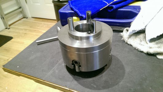
I got a new 4 jaw chuck and I had to mount it on the back plate. So I roasted the chuck at 300 deg until tender and then I test fitted it.
It slipped right on to the back plate with minimal slop. (notice, no mounting holes)

32185692211_fd2b80e9b4_h.jpg

Great! So I turned it over and drilled centering marks for the bolts that will hold it to the back plate. Then I removed the back plate for drilling....not so fast.
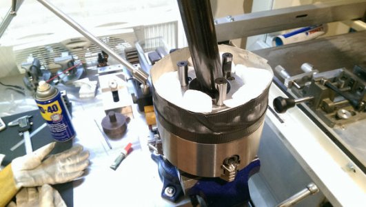
The back plate had heated up and now was friction fit to the chuck!!! It would not come apart! After some thought I came upon a plan. Dry Ice!
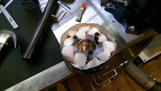
I made a dam around the back plate and filled it with dry ice.

32266546776_f9aea3e392_h.jpg

After it cooled I tried to pry the back plate off.

32156154032_befb232cd6_h.jpg

Damn if it didn't work! The back plate came right off.
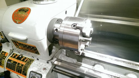
I drilled the bolt holes and reheated the chuck and mounted it.

31495903253_b169687161_h.jpg

If you ever have trouble with an interference fit, dry ice may be your best friend!

Robert
 
Last edited:
Freezer and a heat gun can work very well also. These methods can really cut down on component wear on items that need to come apart more than once, i.e. bearing hubs & races, shafts & gears, or rollers, etc.. Almost like magic. The new chuck looks great on there. Mike
 
Back
Top