2016 POTD Thread Archive

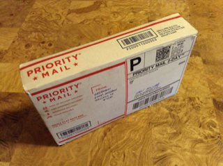
32b71c3b11cf8db0183feed9428d4da5.jpg

Christmas came very early this year. :)

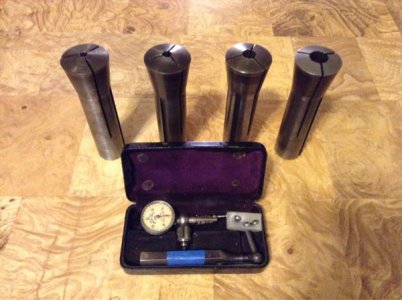
9873ed212e1dab9e5eec87f1963c3639.jpg

I realize that a set of four R8 collets won't excite most people here, but it's very cool for me. I posted in its own thread about my brother offering to pass his RF-30 type mill on to me, but not having any tooling for it, and an incredibly generous user here contributed his extra collets and, quite unexpectedly, a Starrett Last Word dial test indicator. Not sure if he wants to be named so for now I'm not going to (and I assume the image is too small to read it here).

Now I'm wishing I had worked on the mill stand instead of the grinder with my one hour in the shop today. :)
 
No scavenging on our dumps, they go ballistic if they see you pick something up.
 
Not really a project of the day ........ more like project of the month, but last week I finally finished my first real machining project with the new lathe and mill. I got all the new pins and bushings made for the Bobtach rebuild. Put it all together and I can't believe the difference. It's a new machine!!!! Before the rebuild the leading edge of the bucket would flop up and down about 4" to 6" and now there is no movement. I saved about $2000 in machining costs, just for the boring part of the work (no parts) and I got a practical introduction into machining. Between the quoted boring costs and the prices I was quoted for the some of the parts, I figure I saved about $2500.

I'm getting closer to justifying the purchase of the lathe and mill. :) When I bought these machines, I jokingly said I was spending a bunch of money so I could make a $5 part, instead of buying it. But there is no better feeling than the satisfaction that comes from the independence of being able to make something yourself, rather than buy it. Money well spent! ;)
 
Tried a bit of steel milling in my lathe today.
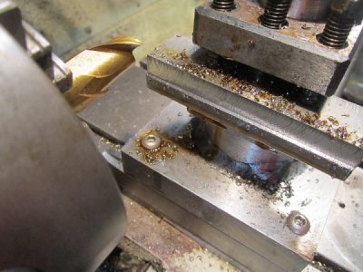
First I faced off all 4 sides of a chunk of steel, then swapped the qctp for the old 4 way and bolted it into that.
Somewhat serendipitously the bottom edge of the cutter was in the exact position I wanted without any shims needed.
milling-1.jpg

After a couple of passes and it could be measured I made a small adjustment to ensure it was cutting even.
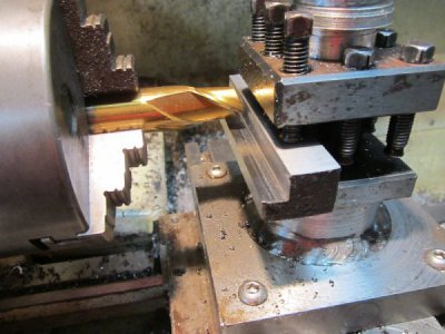
I took cuts at approx 0.5 mm until----
milling-2.jpg
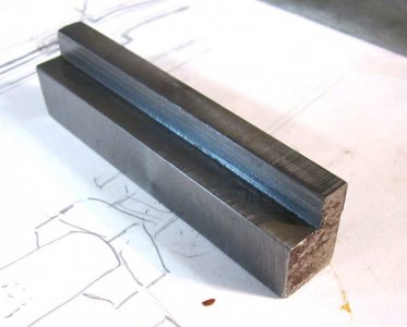
Now I only have to cut it into sections and drill them to make clamps for a small vice I want to bolt to my vertical slide.
milling-3.jpg
 
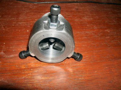
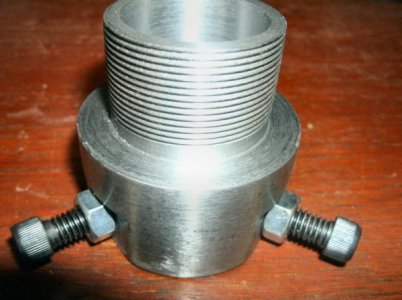
But the left hand threads on the original drive wheel side of the motor mean that if I run it from that side in the position I had it mind, then it will tend to unscrew itself. So what way would you solve that? I would rather not pull the shaft and mount it in the lathe, though I suppose that's an option. Do you think a couple of setscrews would be sufficient? Maybe if I bore and internally thread the drive wheel (just a chunk of home brew aluminum alloy), and add the set screws, then mount it and drive the set screws in to mark the shaft, and then grind flats at those points?
Your proposed solution - marking with the set screws and grinding flats on the motor shaft - should work well. Another option is to pre-drill the drive wheel, use the hole as a guide to drill through the motor shaft, and drive in a roll pin. Another is to use a "dutch pin," though this might not work as well as if the shaft and drive wheel were both steel (or both aluminum).
Making things from things on hand is so much more complicated than just designing with whatever you care to order or build. :(
Shucks, Jon ... that's where the real fun comes in ... though I do miss the days of being a machine designer at HP and just ordering what I needed. Strange how "funny money" becomes all too real when you have to pay for it yourself! Of course, even then you still had to get part A to mount on and play nicely with parts B, C and D!

PS - Very strange thing ... when looking at your posts on the forum, the photos are replaced by little icons with a red X through them. But when I inserted your post as a quote, the images showed up correctly.
 
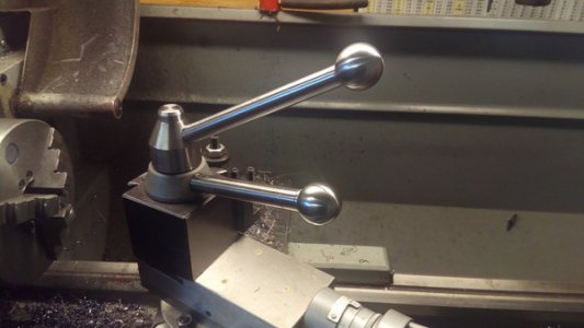
Two new handles, and replaced the lock nut on my tool post. I always hated having to pick up that wrench every single time I needed to adjust my tool angle. It's one of those things that I've been meaning to do for years, but never found the time. Today...I made the time. The lower handle for the quick change release was at 15 degrees from the factory. I made the tool post lock down one at 30 degrees. It works pretty slick....and best of all.....no wrench required. :)


IMG_20160605_183257_zps2mmqdbhh.jpg
 
Your proposed solution - marking with the set screws and grinding flats on the motor shaft - should work well. Another option is to pre-drill the drive wheel, use the hole as a guide to drill through the motor shaft, and drive in a roll pin. Another is to use a "dutch pin," though this might not work as well as if the shaft and drive wheel were both steel (or both aluminum).

Shucks, Jon ... that's where the real fun comes in ... though I do miss the days of being a machine designer at HP and just ordering what I needed. Strange how "funny money" becomes all too real when you have to pay for it yourself! Of course, even then you still had to get part A to mount on and play nicely with parts B, C and D!

PS - Very strange thing ... when looking at your posts on the forum, the photos are replaced by little icons with a red X through them. But when I inserted your post as a quote, the images showed up correctly.
Tapatalk seems to be having trouble today. The images show up just fine for me when viewed in the Tapatalk app on either of my devices (only one of which I use to post photos through that app), but not on the web view. They're also uploading VERY slowly today. I'm hoping it gets resolved soon.

Yes, there's still a challenge when dealing with parts ordered from a catalog, but I would much rather handle things that way if I had the budget for it. The powder coating oven was done that way. Standard motor mount size, standard coaxial fan bolt pattern, standard pulleys on standard shafts with standard keys and keyways, etc. When the manufacturer's tech flew out from Alabama to install the final control module and calibrate the system I finally I got to see it run for the first time. It absolutely purred. Not the slightest vibration or other problem. He said it was the only startup he had ever done where he didn't have to fix the installation. Said they usually shake so badly that it would rip the concrete anchors out if he let it run. I can see that with home brew builds, but with known compatible Dayton parts shipped straight from Grainger?? No excuse to not work the first time. Just install everything to spec.
 
the problem with modifying something you built...you forget about the problems you had in the first place....had to shorten a wheel post forgot that it hit the motor beneath ... repositioning motor now...:idea:


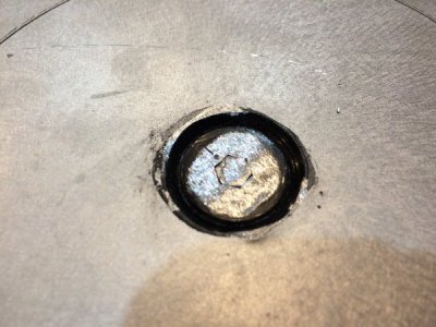
and this bolt will never come out...EVER... I forgot I used red locktite...my little Milwaukee 12 volt cordless band saw fixed up my issue quick enough without the need to remove it..

IMG_9722.JPG
 
Back
Top