-
Welcome back Guest! Did you know you can mentor other members here at H-M? If not, please check out our Relaunch of Hobby Machinist Mentoring Program!
- Forums
- THE PROJECTS AREA
- PROJECT OF THE DAY --- WHAT DID YOU DO IN YOUR SHOP TODAY?
- Project of the Day Mega-Thread Archives
You are using an out of date browser. It may not display this or other websites correctly.
You should upgrade or use an alternative browser.
You should upgrade or use an alternative browser.
2015 POTD Thread Archive
- Thread starter jumps4
- Start date
- Joined
- Apr 1, 2013
- Messages
- 1,142
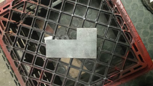
WHAT IS THIS TOOL, AND WHAT DO YOU CALL IT.
this is not a super complex project I know. I am only posting this one as it is a quick clever tool I use from time to time. I did not invent it (could have roots back to ancient Egypt) I do not even know the name for it. But I thought some of the newer guys into welding might find this idea useful, not that it can only be used in welding . ONE more hint it is used in conjunction with two of the oldest tools I know of and one of those tools rely on the other for force.
Mark
this is not a super complex project I know. I am only posting this one as it is a quick clever tool I use from time to time. I did not invent it (could have roots back to ancient Egypt) I do not even know the name for it. But I thought some of the newer guys into welding might find this idea useful, not that it can only be used in welding . ONE more hint it is used in conjunction with two of the oldest tools I know of and one of those tools rely on the other for force.

Mark
- Joined
- Aug 23, 2014
- Messages
- 932
Made a replacement idler pulley for my sons ride on fertilizer spreader. He needed to use it Monday for a big job and no parts are available locally. His boss threw out the old pulley, my son told him we can make one but we need the old pulley to get dimensions. So the boss got it out of the trash. The pulley is 3" in diameter and 1.3" thick. used a HF 7x16 lathe to turn it. Not the quality of the machinists on this forum, but decent for me. The chatter marks are from the A R Warner boring bar triangle insert. I used the flat edge to get a relatively flat bearing seat. Saved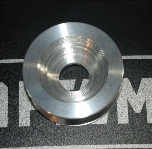
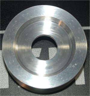
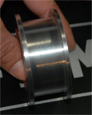
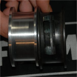
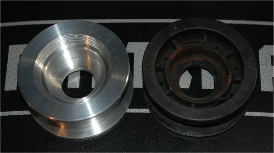 my son from having to walk the 6 acres behind a manual spreader. The old pulley is shown in the last two photo's. The old bearing looked as though it was sitting on the ocean bottom for a couple of years. It was replaced 6 months ago. The circular ridges are where I tapered the entrance to the bearing bore and back side of the pulley bore for looks only. 6061-T65 Aluminum.


 my son from having to walk the 6 acres behind a manual spreader. The old pulley is shown in the last two photo's. The old bearing looked as though it was sitting on the ocean bottom for a couple of years. It was replaced 6 months ago. The circular ridges are where I tapered the entrance to the bearing bore and back side of the pulley bore for looks only. 6061-T65 Aluminum.
- Joined
- Nov 24, 2014
- Messages
- 3,199
At first blush I couldn't figure out what I was looking at in the picture showing the original idler. I imagined the original was cast iron and I wondered how aluminum was going to hold up.
I think I've figured it out now. The original is plastic and the first picture shows the groove worn through after the bearing froze. Is that correct?
In the last photo, rotating the original about 150° CCW would clearly show what was going on.
My project for the day was helping you tell your story.

Last edited:
- Joined
- Aug 23, 2014
- Messages
- 932
Yes you are correct. The original was plastic. When the bearing seized the belt cut a groove in it. I should have mentioned the plastic. Yor project of the day beats the heck out of mine.At first blush I couldn't figure out what I was looking at in the picture showing the original idler. I imagined the original was cast iron and I wondered how aluminum was going to hold up.
I think I've figured it out now. The original is plastic and the first picture shows the groove worn through after the bearing froze. Is that correct?
My project for the day was helping you tell your story.
- Joined
- Sep 23, 2015
- Messages
- 170
I spent the early hours of the day with my Craftsman 12 X 36 lathe. I make disc brake conversion kits for vintage Mopar cars and trucks. The larger Chrysler and DeSoto cars have a spindle with diameters that are no longer supported by tapered bearing manufacturers. I turned a pair of spindles to current bearing diameters and put one more old Mopar back on the road with brakes that will make it driveable today! A very satisfactory use of a couple of early morning hours!!! Add a large cup of very hot tea and all is right with the world!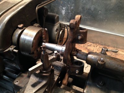

I would like some opinions on an easy project that may be very useful, if it will work. I like to use collets a lot but the South Bend 9 inch does not readily accept 5C collets. I know I can go buy a 5C collet chuck and back plate and spend around $250 for the setup, but being the cheap.....err I mean thrifty individual I am , I came up with a simple solution at zero cost by using scrap pieces lying around. I would like some opinions on the feasibility of the design.....or in other words..... does anybody else think this will work? Below is my concept drawing of this idea.
The chuck body is a simple one piece of steel. The draw bar extends out the rear of the spindle and pulls the collet into the body to tighten by screwing into the internal collet threads.. I am thinking about a needle thrust bearing between the draw bar and chuck body to make tightening easier.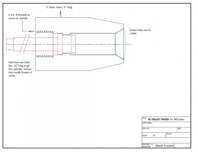
.......working from my bed until I can get back into the shop.
The chuck body is a simple one piece of steel. The draw bar extends out the rear of the spindle and pulls the collet into the body to tighten by screwing into the internal collet threads.. I am thinking about a needle thrust bearing between the draw bar and chuck body to make tightening easier.

.......working from my bed until I can get back into the shop.
- Joined
- Feb 17, 2013
- Messages
- 4,407
I'd suggest not making a shoulder on the drawbar inside the chuck body. Instead, add a shoulder (see also below) to the far end of the drawbar, where it exits the spindle. If nothing else, you'll have a larger diameter for the needle bearing. You might even want to fabricate a drawbar centering collar to fit inside the far end of the spindle, with a nice large flange at its outer end for the needle bearing.
Finally, instead of machining the "shoulder" as part of the drawbar, you could fabricate it as a separate collar, which you can secure to the drawbar with a pin AFTER you have all the parts built and test-ssembled. That way, it can be located in an ideal place to allow tightening the collet.
Finally, instead of machining the "shoulder" as part of the drawbar, you could fabricate it as a separate collar, which you can secure to the drawbar with a pin AFTER you have all the parts built and test-ssembled. That way, it can be located in an ideal place to allow tightening the collet.

