@Provincial
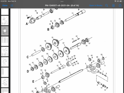
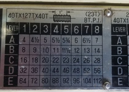
Jock, I will take a look. Yes, the F shaft is an option and I do not find it being uses elsewhere either. So I have been ignoring it. I did not use it in my analysis of the JET machine either. The 1340's have an 8 TPI lead screw but the 1440 has a 4 TPI lead screw. Your name plate implies that your lead screw is 4.5TPI not 8 or 7. The more important issue is that for the FEED drive both machines use the FEED bar which only has a notch down the center, no threads unless you want to call this a "0 TPI" lead screw. I have been calling it the FEED Bar. Also important is that your cross feed is an 8TPI where has the other machines are 10TPI. Are you sure about this? From your plate you have 8 fundamental threads and 5 factors of two multiples, which is pretty standard. The PM1340 also has 8 and 5. But the fundamentals for the PM1340 are: 4, 4.5, 4.75, 5, 5.5, 6, 6.5, 7. Your machine is slightly different: 4, 4.5, 5, 5.5, 5.75 6, 6.5, 7 as it is missing the 4.75 but has a 5.75 instead.
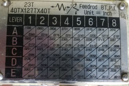
I looked at the FEED rate table. I believe that if you use the first row of the TPI table in the following formula you will get the exact FEED rates:
(0.1005/(TPI#)*(4)). So if you use the exact number and take ratios x-feed rates you will find variations ranging from 2.809 to 3.071. Some simple observations: However if you only look at the TPI which are 4,5,5.75, and 6 you will find you get pretty good agreement at 2.903. That is not to say that this number is correct. It may just be a coincidence. However for TPI 5,5.75, and 6 your get exactly the same number each time: 2.903043478. However you will note I normalized these by the first feed rate of 0.1005/4. If instead you used the 5 TPI value, to do the normalization 0.0805/5 you find similar effects but the ratio of feed rate to x-feed rate changes a bit to 2.913043478. So who is to say which is correct. I cannot say for sure if this is different from what you measured or not. Maybe you can.
I am not for sure how to proceed, since when I look at the photos in the JET book the spindle and change gears to not appear as you described. they look considerably different, but it could be that they just have different gears mounted. Perhaps you could write this a bit differently for me telling me which gears touch the next gear when you are set up to get the 4 TPI thread. Please make the Spindle gear the last one (50T) in a string of touching gears. Or maybe a sketch of how they mesh. If there is an intermediate gear between only two then it has no effect 40-127-40 on the over all turns ratio as the two 40T gears turn at the same rate. . For example starting from the input to the gear box: 40 to 127 to 40 to 50 to 26 which is tied to 21 and then the 21 to 50 at the spindle? Or is it that the go 40 to 127 to 40 to 50 to 21 which it tied to 26 which touches the 50T spindle? So in the first case the ratios read: (40/127)*(127/40)*(40/50)*(50/21)*(26/50). We see that the over all ratio is simply (40/21)*(26/50) . i.e one turn of the shaft into the gear box results in (40/21)*(26/50) turns at the spindle or 0.8*(26/21)=0.9904. Where as the alternative yields (0.8*(21/26) = 0.64615.
Lastly you might count the length per tooth on the RACK. It turns out to be important. In the JET manual it says it is a 2mm thread so the length per tooth is just 2mm*Pi()=6.2832mm. This 2mm comes from the JET manual 2mm, 13T gear that is suppose to be engaged to the RACK. When I did mine I it seemed that the gear teeth repeated pretty well at 330mm with 70 teeth counted. 330/70=33/7=4.7143 ==> 1.5mm*pi()=4.712389mm.
I too am going to be out of the loop for several days starting tomorrow.


