Wellllll I Guess I Am Going To Cnc My Enco 45 But Slowly

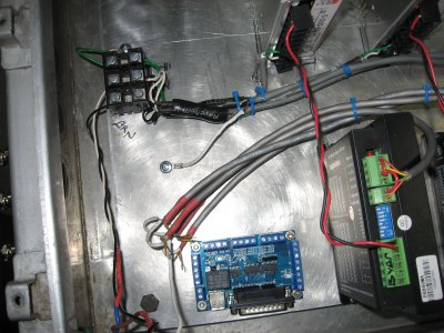
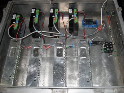
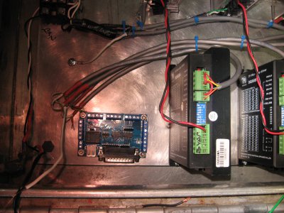
Well guys have gotten some wiring done and would like you guys to check it out BEFORE i fire it up, do not want to loose the magic smoke out:chemist:
Any how here are the pic,s
Bill

Consider this 'tough love', some of your wiring sucks. In the pics I see poorly stripped wire, too much insulation stripped with exposed wire, a couple of very poorly soldered wires that are not soaked through with solder, jumpers that are way too long, exposed shields that should be covered in heat shrink, there is room for improvement my friend. These CNC builds can be tricky enough to troubleshoot, take the marginal amount of extra time to do your wiring well to avoid chasing wiring issues later on. ;)
 
Consider this 'tough love', some of your wiring sucks. In the pics I see poorly stripped wire, too much insulation stripped with exposed wire, a couple of very poorly soldered wires that are not soaked through with solder, jumpers that are way too long, exposed shields that should be covered in heat shrink, there is room for improvement my friend. These CNC builds can be tricky enough to troubleshoot, take the marginal amount of extra time to do your wiring well to avoid chasing wiring issues later on. ;)

This was all temporary lash up to find out if all components worked and was NEVER meant as a finished product ever.
Even the power supply's are not wired in the permanent configuration as they draw 6 amp per unit and ether need a relay or split circuit to run at that load. This whole exercise was to see if all the components would play nice together and worked as there is always a question on ANY Chi-com products working at all and the testing is finished and has been knocked down for final assembly
I am familiar with good soldering practices as a advanced class ham radio operator but was grateful to Steve for the help and did not want to waste his time with mundane project of finished product, this would have been liken to a breadboard test, nothing more.:agreed:
Thank you for your feedback and when I get the control panel done I will post the pictures and I would appreciate any feed back I can get.:penny:
Bill
 
Have been busier than I care to admit, I have started making motor mounts and cleaning up the wiring (in between the Honey dooos) and hope to have some pictures to show soon showing the progress ( I said the build would be slow).
Had another run with the vertical band saw and tried to get rid of my middle finger on my right hand, DAMMMMM that smarts.:bawling::bang head::cussing:
Bill
 
Well I have all the harnesses for the power supply's and drivers all cleaned up and now have hit a bump in the road with the Bob as the DB25 and usb need to be accessed from outside the main panel which means I will have to hand fit the Bob into the side of the panel as I am not blessed with anything else to cut it out with but drills, jig saws and files. (reminds me when I was working with ham radio projects)
I have laid out the first stepper motor mount and am about to cut them out and mount them. (will take pics and post)
Bill still doing it slowly.:pickaxe:
 
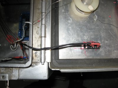
Here are some pictures of the elect. panel I have been working on and am now trying to figure out the DB25 and USB access on the panel.
Not much but I am moving again.
Bill IMG_3666.JPG IMG_3664.JPG IMG_3665.JPG IMG_3667.JPG
 
Wiring looks a lot better, note its a best practice to bring all of your grounds back to a single point in the chassis and to use star washers that bite into the metal.
 
Wiring looks a lot better, note its a best practice to bring all of your grounds back to a single point in the chassis and to use star washers that bite into the metal.

That aluminum Plate is a common point as far as my 74 tears of life has learned me me about electrical grounding but never to old to taught sumptin new but this setup will suffice for the job its doing me think, the grounds are tagged together as a rule if you look at the white shrink tub covering the ground lead not yet attached by the BOB board.:agreed:
The screws I use for grounding have built in teeth like a star washer so not needed:agreed:
How about any ideas about mounting the BOB inside the case and easy access for the USB/DB25 cables????????????????:penny:

I worked fo a lot of years in the Vancouver area, are you native to that area? Do you know a older gent there named Ray Wohorten ?? (spelling??)
Scuba dived into battle ground lake crater way back when, dam that was cold down there.
You a member of the Clark County Radio Club? I used to spend much time with field day outings and such with them.
Bill
It's conventional to put all the grounds on one bolt but the way you've done it will work fine.
 
That aluminum Plate is a common point as far as my 74 tears of life has learned me me about electrical grounding but never to old to taught sumptin new but this setup will suffice for the job its doing me think, the grounds are tagged together as a rule if you look at the white shrink tub covering the ground lead not yet attached by the BOB board.:agreed:
The screws I use for grounding have built in teeth like a star washer so not needed:agreed:
How about any ideas about mounting the BOB inside the case and easy access for the USB/DB25 cables????????????????:penny:

I worked fo a lot of years in the Vancouver area, are you native to that area? Do you know a older gent there named Ray Wohorten ?? (spelling??)
Scuba dived into battle ground lake crater way back when, dam that was cold down there.
You a member of the Clark County Radio Club? I used to spend much time with field day outings and such with them.
Bill

Your BOB isn't designed to be panel/chassis mounted that's the issue. I would mount it internally where it makes the most sense, then run a cable from there over to a panel mounted coupler for the USB and DB25. That gets you through your cabinet to the outside world, just connect a cable from there to your computer.

For the USB I would use something like this so I could just drill/punch a round panel hole for it http://www.amazon.com/Switchcraft-E...sbs_147_9?ie=UTF8&refRID=0C4G79KJHFJ19AY3XF04

Go to Digikey's web site, search on DB25 and have a look at the "housings" here's an example that might work for you. http://www.digikey.com/product-detail/en/205165-1/1122-1149-MIL/132220

When building vacuum tube guitar amps you have to be quite careful about the grounding scheme and AC power routing so that you don't have 60 cycle AC hum coming out the speakers. You can induce AC hum by routing AC power too close to signal wires or components. Poor placement of the transformers in the chassis. You can induce AC hum by poor chassis grounding schemes grounding signal carrying components down stream of large current AC power sources, where the chassis has become a ground wire basically.

There are a number of best practices, twisting AC pos/neg wires together for example so that they cross each other a few times per inch, a cordless drill is a good tool for this. Here's another tip, discover "top coat" wire, its still flexible and comes on a spool but has a top coat of tin so that if you bend it into a shape it holds that shape. With Teflon insulated wire the top coat is less effective but helpful. You can find this type of wire for sale by suppliers who cater to guitar/amp builders. Shoving twisted pair AC power wires into the corner of the chassis e.g. the corner of the chassis provides a bit of shielding. Where you have to cross an AC power source with a signal wire cross it at a right angle vs say running them parallel to each other.

Many have probably hear a guitar amp humming loudly but its entirely possible to build a 100 watt monster amp with zero hum. On my first successful build I wasn't hearing any hum at all, turned the amp up to like 8 and all I heard was some white noise hiss, thinking something was wrong I hit a cord and about blew my ear drums out. Don't let the 100 watts fool you, for a tube amp that is stadium concert loud as all hell.

Possibly overkill for wiring up a CNC control box but proper layout of components with some logical thought to separating large AC currents from small, or AC from DC is a cheap way of avoiding glitchiness.
 
Last edited:
Back
Top