Watch your "spring" passes!

I totally agree with you - burying the nose radius is the best way to minimize radial forces for a consistent cut. I do not know of a source for CCGT inserts that fit a 1/2" bar with tiny nose radii. That is why I suggested contacting one of the insert makers; they may have some we don't know about.

If you choose to go with a carbide bar at some point, watch ebay for a Circle Machine QCMI bar. It takes flat-topped boring, grooving and threading inserts. These bars are really versatile and very accurate. You will also find that a flat insert will take a much finer cut than one with a chipbreaker. With the right speed and feed, they produce coiled chips instead of long strings, even in aluminum. I totally gave up on SCLCR bars a long time ago; they cut but not nearly as well as a Circle bar does. Moreover, Circle tends to make insert with smaller nose radii and that really helps at these tolerance levels.

Good luck with this project and let us know how you make out.
 
you can get CCGT 32.50 inserts off eBay for not much money - those will help reduce cutting force and bar deflection. Also, if I'm trying to hit a critical bore dimension I'll do most of the cuts at the heaviest DOC I can up to say 0.5mm depth and width from final dimension. Then enough spring passes at that same ID until no material is removed, then measure. I'll then face the bottom of the bore to full depth and take a 0.1mm cut off the ID. Measure, cut again, until dimension is achieved. If you have the mating part, I often use that as a go-no go gauge when I'm getting close, just in case I do something stupid with the measuring.
 
...I needed an accurate depth to the bottom of the bore 3.708 +/- .002" so I had to use the compound slide on the lathe rather than the carriage (I don't have a DRO...

Do what I did...mount a long-travel dial indicator to get accurate carriage travel. I have one 2" and one 4" travel. I zero the boring bar insert on the workpiece's face and can control depth to within 0.001".
 
This is a really good discussion -- thanks to all contributors! I've learned a few things here this morning, much appreciated...

MetaKey
 
Am I missing something here ? Why not bore your 3 diameters on the right side in one set-up and face perpendicular , remove your part , turn up a spud ( step mandral ) and locate off 2 bores and the face and bore your last diameter . Concentric and perpendicularity are guaranteed . ;) Do it all the time .
 
Am I missing something here ? Why not bore your 3 diameters on the right side in one set-up and face perpendicular , remove your part , turn up a spud ( step mandral ) and locate off 2 bores and the face and bore your last diameter . Concentric and perpendicularity are guaranteed . ;) Do it all the time .

That probably would have been good. I have a lot of experience on the mill, but newer to the lathe. Learning what makes sense as far as order of operations takes a little while. In hind sight:
  1. Square Stock
  2. Drill 4 mounting holes, 2 through holes, 2 CBores
  3. Drill and bore all 5 features from one side (motor pilot, large bore, clearance bore, bearing bore, and through hole)
  4. Flip, drill and bore the opposite bearing pocket
 
Project update!

Used the long weekend to get an extra hour or two in the shop. Turned a plug to 1.2503, bored the part to 1.2499, nice press fit with a few whacks from a dead blow mallet. Rebored to 1.0236 and hit it dead on size (as close as I can measure). Used the 3/4" boring bar with no trouble at all!

Then I turned a simple arbor and pressed in the angular contact bearing (it was a nice light press). I did some thinking and realized I shouldn't have put the bearing in since I have another op on the mill and then sanding, polishing, and painting. Went to tap the bearing out and BAM!, I separated the inner race and balls from the outer race :rolleyes:.

Now I have a bearing race stuck halfway in my hole with no obvious way to remove it (too small and deep to fit a bearing puller). I will have to think that one through. I still hear my dad telling me to slow down and think lol.

Thanks for all the advice!
 
Then I turned a simple arbor and pressed in the angular contact bearing (it was a nice light press). I did some thinking and realized I shouldn't have put the bearing in since I have another op on the mill and then sanding, polishing, and painting. Went to tap the bearing out and BAM!, I separated the inner race and balls from the outer race :rolleyes:.

Now I have a bearing race stuck halfway in my hole with no obvious way to remove it (too small and deep to fit a bearing puller). I will have to think that one through. I still hear my dad telling me to slow down and think lol.


LOL ! That won't be the last time that happens ! ( And I'm laughing with you and NOT at you ! :hammer:

They have many part in here at wok similar to the part you are making . I take an end mill and cut 2 slots thru the bearing spacing bore to get a pin punch onto the outer race . Those little bearings sure go in easy but are a RPITA to get back out .:eek 2:
 
Last edited:
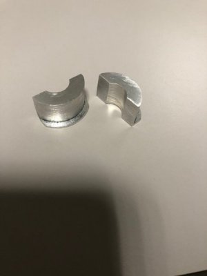
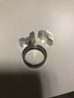
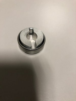
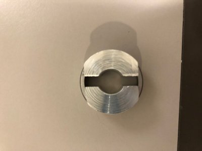
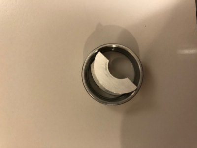
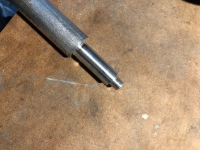
OK, so I salvaged the part in what I think was a creative way. I turned a collar on the lathe which was just small enough to slip through the outer race of the bearing, and I included a lip on it which went under the race (which I had already knocked out .050 before it fell apart). I split it into two pieces using a hack saw and filed them until they could pass through the bearing and be "assembled" behind the race. I turned a long mandrel which fit into the center hole of the collar and I was able to knock the race out without damage to the part. All told it took 30 minutes!

2.jpg
3.jpg
4.jpg
5.jpg
6.jpg
1.jpg
 
I signed up here to read/save a download about correctly grinding HSS tool bits and within days get to see a solution for a problem I have in a gearbox - removing bearings that were driven in from each side against a shoulder = Thank you for posting the pictures and the idea
 
Back
Top