- Joined
- Dec 27, 2014
- Messages
- 4,087
Was the hole OD enough that you could have used a larger/heavier boring bar to finish?
Was the hole OD enough that you could have used a larger/heavier boring bar to finish?
If I'm understanding you correctly, you're boring on the lathe and you have two bores back to back in the same part


Looking at that part, wouldn't it have been easier to bore straight throughfor both bearings at one size and then press in a sleeve for the spacing between them?Mikey,
Thank you for the detailed response. I don't feel criticism at all, in fact I am still plenty new to all of this (
You are correct about the part, there are several features on this part, but the critical ones are the back to back bore which hold a pair of angular contact bearings. Concentricity is critical here as any runout between the features would cause uneven loading on the bearings and poor alignment of the ballscrew. I chose .0005" as an attainable value, however I'm trying to hold as tight as I can. The axial distance between the bores is slightly less important, but I wanted to hold better than +/- .005" so I opted to use the compound slide. I gave a .002" tolerance, but it was less critical than the bore.
I agree it was tough to hold these tolerances, but the smallest diameter hole through the part was cut in the same setup as the backside bore which allowed me to indicate it when flipped (The indicator was completely inside the part to reach!).
My plan for sleeving will be to use my 3/4" x 10" steel boring bar, as T Bredehoft commented above. I have confidence I will be able to hold the tolerances with a little more care than might have been given before. I will one day invest in carbide bars, but I can't stomach the costs right now, so a little more skill/luck/care will be required. My bar is a SCLCR with CCGX 31.51 (1/64" radius) or CCGX 31.50 (1/128" radius), I can't remember which I have mounted currently. I have been using these razor edge ground inserts for a while now with good luck. I really can't get them to rub even when taking
You are correct about the use of the compound slide for depth control. I have been thinking of making a carriage stop, so I may have to bump that up on the roster of projects.
In answer to your thoughts:
I agree that I was surprised to be that much oversize. I might be exaggerating the impact of the spring in the bar and there may be other factors at play here. I think with the equipment I have, I am happy when I hold within .0005" on diameter.
- Temperature was kept nominal by the very slow cutting speed, small depths of cut, and application of coolant. I agree it can mess with measurements, but in the case of a bore, wouldn't that tend to undersize the bore? I very well could have screwed up the measurement, we all know I have done that before. I personally don't love the "feel" type of measuring instruments like the telescoping bore gages I used, however I had no other way to measure the bore deep in the part. I would prefer a direct reading 3 point bore gauge, however the money is better spent elsewhere.
- Insert is relatively new but has removed some material. I don't know if the break in is as important as it is on inserts for tougher materials, but it is a thought. The insert is sharp and has no damage.
- I've goofed plenty before so I can't rule that one out! I didn't think I missed it, but 8 thou is a serious discrepancy.
- Cutter was backed off the material before backing out of the bore. I never reverse cut.
Thanks for all your thoughts!!!
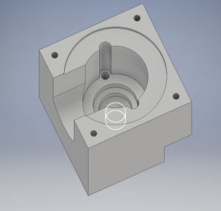
Here is a model of the part:
View attachment 274627
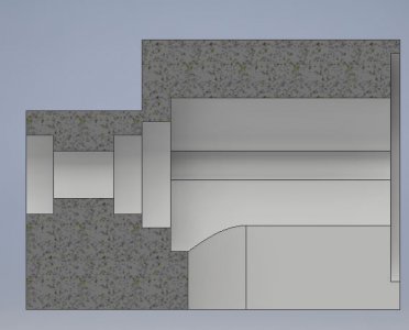
And a cross section showing the bores:
View attachment 274628
Looking at that part, wouldn't it have been easier to bore straight throughfor both bearings at one size and then press in a sleeve for the spacing between them?
Sent from my H3123 using Tapatalk
