The Giant Binocular

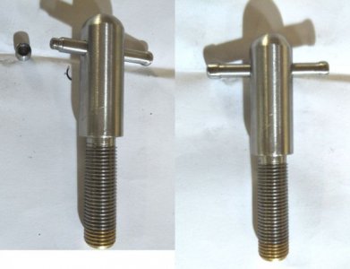
This is for the azimuth brake, it screws down through the plate the altitude bearings are bolted to.
The brass tip has an internal M8x1 thread lock tighted in, the external thread is M12x1.25 single pointed.
Hopefully the brass tip will rub against the top of the steel disk the main bearing sits in giving a brake.
There will be two of these opposite each other with the one to the rear permanently on sufficient to produce drag with the front one adjustable.
I want to cross drill for a tommy bar but need everything assembled so I know where it will lie when fully locked.
az-brake.jpg
I had made two more of these but sheared the brass screw off just as it fully mated so had to dump them
 
Suggestion: On the one used as a drag brake, you might want to drill into the side of the thread and insert a small nylon or other plastic plug, so that the screw will hold its adjustment.
Screen Shot 2019-04-11 at 12.24.47 PM.jpg
 
I had been racking my brain for a nylock type of thing, excellent suggestion, thanks.
 
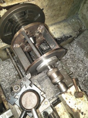
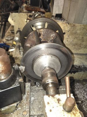
I had to resort to a hand powered lathe for this part.
The brass footed brakes rubbing on what I thought was a smooth surface gave a lie to that assertion.
There were slight high spots above all the welded spacers so the movement was more a stick and go stick and go.
A pipe centre in the chuck and a standard live centre in the tailstock held it in the lathe.
bearing-blocks-5.jpg
Obviously the chuck wouldnt power the assembly so I had to spin it by hand pulling it towards me sharply.
The weight of the unit acted like a flywheel so I could take a very fine cut in tiny short amounts until I had a smooth path for the brake shoes to rub against.
bearing-blocks-4.jpg
This was a long process due to the tiny amount I could remove per spin but it was worth it as now the brakes rub smoothly with no stops and starts.
 
Not very much done of late.
Drilled and tapped all the holes to hold the alt/az bearing assembly to the pier.
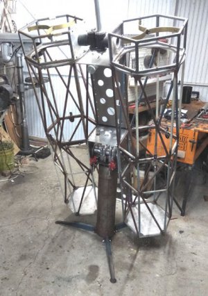
Then bolted it all together to see how it looked.
The disk brake idea is awesome, so smooth with steady friction up to total lock.
Its not balanced yet as there are no mirrors or mirror cell in place yet but there appears to be no no slop or backlash in the altitude bearing.
Bloody ell, its a big scope. I will need 3 steps to get high enough to view the zenith.
big.jpg
 
Ya know, you CAN make viewing easier by shortening the focal length on your mirrors. Although I’ve climbed15-20 feet in the air to look through some of them in the past. I’m just gettin’ too old and shakey and want my feet well anchored to terra firma anymore. I’m even beginning to construct a comfy lay-back pivoting recliner chair for viewing through my 4-1/2” binoculars. I just hope I can stay awake.

The Grumpy OLD guy
 
yeah I know. Todays trend is for larger and faster scopes giving reduced height.
I decided upon f6 to minimise the secondary obstruction size as they have to be way larger than a standard scope in an attempt to maximise contrast.
Also f6 is easier to figure if the distortion/pulling system fails.
When I plotted the numbers for f5 the secondary became almost half again as large.
I will use a three step with extensions to lean against. Annoying but then its only for the zenith, most of the time I expect to be observing around 5-10 degrees off vertical so hopefully it will be ok.

A pivoting recliner on a turntable with a proper bracket supporting the bins is awesome but the turntable takes up a lot of room in the car.
 
I thought that only the cross bar on the main bolt, wrench, etc. was a T- bar. A chuck key for instance has a T cross bar for a lever. Since a chuck key can have a crossbar for leverage it is the chuckie’s Tommy bar. Get it Chuck.?

The Grumpy old guy who is also a Chuck
:crushed:
PS sorry
 
Back
Top