-
Welcome back Guest! Did you know you can mentor other members here at H-M? If not, please check out our Relaunch of Hobby Machinist Mentoring Program!
You are using an out of date browser. It may not display this or other websites correctly.
You should upgrade or use an alternative browser.
You should upgrade or use an alternative browser.
The Giant Binocular
- Thread starter savarin
- Start date
- Joined
- Nov 17, 2017
- Messages
- 1,525
details details??????
Looks very fast.
13" F/3
I am currently building a 20" F/3 in the same general architecture.
- Joined
- Aug 22, 2012
- Messages
- 4,271
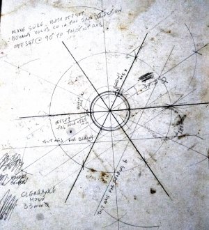
This is what all the palaver regarding dividing up a circle was leading to.
I went for a large circle to improve the accuracy of the smaller circle and it seems to have worked.
The bearings are 6mm dia, with a 3mm hole passing through the 12mm plate I thought it would be good to ensure the middle of the plate coincides with the middle of the 3mm shaft when its tilted at an angle of 5 degrees.
The tilt axis lines are where I hope to line up the part on the 5' jig I made just for these holes.
To get the 5' angle to line up I have to offset the start point 0.525mm
Now for the worry, I will drill and tap the bearing holder holes for M3x0.5, this will only allow 1.5mm between the edge of the hole and the bored out middle for the eyepiece tube. I'm not worried about this as the pressure will be pushing the threaded rod into the plate.
BUT, do I bore the middle then drill and tap the bearing holes or or do the bearing holes first then bore out the middle?
I'm a tad worried of tearing out the edge of the 2.5mm holes but hope a VERY sharp boring bar bit will be the way.
Now to transfer all these measurements to the 12mm plate.
- Joined
- Aug 22, 2012
- Messages
- 4,271
After a lot of agonising on how to set everything up I decided to use the vertical slide on the lathe.
I transfered all the points with a very thin needle through the card to the 12mm plate and re drew all the lines.
This worked very well.
I added a plate at the bottom of the 5 degree jig for the square to sit on to align the axis of the bearing holes.
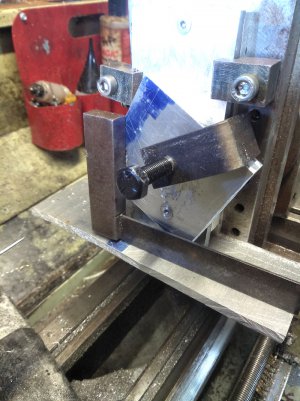
My brass scribe uses a sewing needle and is dead straight so I used that in the collet chuck to line up the start of the hole for drilling.
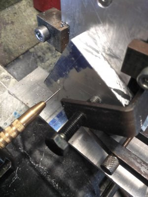
Once aligned all clamps done up tight, swap the scribe for the 2.5mm drill bit and bore the hole.
Then use an 8 mm end mill to make a little bit of clearance for the bearing at the same angle.
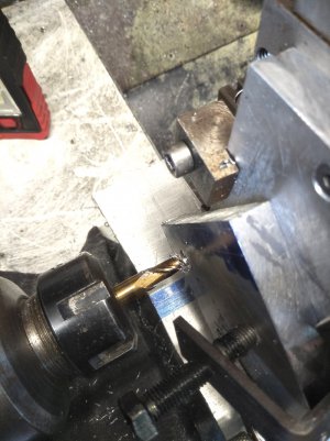
Then swap the endmill for the tap and start it off in situ.
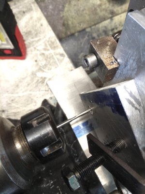
Then finish tapping free hand.
The use of the collet chuck to keep all the processes aligned was excellent.
So did it work?
Yep, here its just hanging on the tube with all 4 bearings in contact.
One revolution produces approx 10 mm of travel.
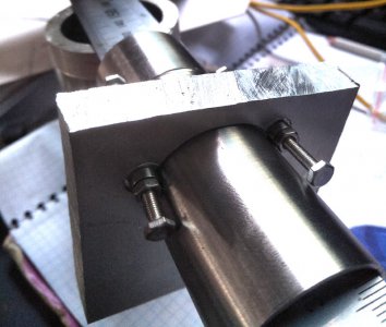
Next job is to open up one end for the fine adjustment block.
I transfered all the points with a very thin needle through the card to the 12mm plate and re drew all the lines.
This worked very well.
I added a plate at the bottom of the 5 degree jig for the square to sit on to align the axis of the bearing holes.

My brass scribe uses a sewing needle and is dead straight so I used that in the collet chuck to line up the start of the hole for drilling.

Once aligned all clamps done up tight, swap the scribe for the 2.5mm drill bit and bore the hole.
Then use an 8 mm end mill to make a little bit of clearance for the bearing at the same angle.

Then swap the endmill for the tap and start it off in situ.

Then finish tapping free hand.
The use of the collet chuck to keep all the processes aligned was excellent.
So did it work?
Yep, here its just hanging on the tube with all 4 bearings in contact.
One revolution produces approx 10 mm of travel.

Next job is to open up one end for the fine adjustment block.
- Joined
- Feb 1, 2018
- Messages
- 1,867
I am not sure anyone has told you about my friend Bill Volna...He also builds telescopes from scratch... Check out his sand box link on the left..
Volna Engineering Facility
Forty-one years of experience in one-of-a-kind solutions to difficult measurement and tooling problems for the aerospace and defense industries
www.volnaengineering.com
- Joined
- Aug 22, 2012
- Messages
- 4,271
Well that didnt work. I've made 4 helical crayfords in the past and they all worked perfectly.
I took extra care to ensure the shafts for the bearings were correctly alligned but somehow screwed up.
The eye piece tube canted, bah humbug.
so now I will make a helical focusser.
I took extra care to ensure the shafts for the bearings were correctly alligned but somehow screwed up.
The eye piece tube canted, bah humbug.
so now I will make a helical focusser.
- Joined
- Aug 22, 2012
- Messages
- 4,271
To make the helical focusser I decided upon a 1mm thread pitch cut at 4mm lead.
This gave me a 4 start thread of M1 pitch where 1 turn gave 4mm of travel.
The hardest part was getting the top slide perfectly aligned with the ways so 1 turn of topslide lead screw went exactly 1mm
I used the hand crank to turn the spindle,
First thread cut to depth then back to the start without disengaging the half nuts.
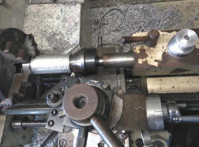
Advance the top slide 1 full turn (=1mm of travel) and cut the second thread
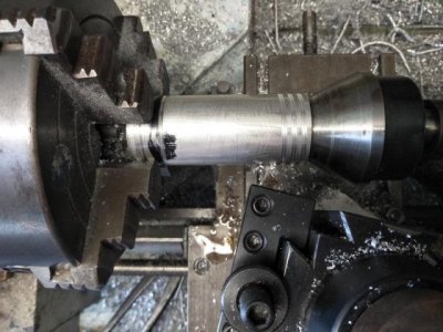
And continue for the third and fourth cut.
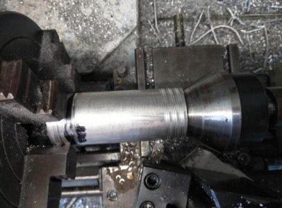
To cut the internal 4 start thread I kept the settings for a 4mm pitch but used an M10x1 tap silver soldered to a bar.
I opted to try this as all 4 starts are cut at the same time so I could use the part above as the test fit to get the correct dia and thread fit.
Again I used the hand crank and didnt disengage the half nuts.
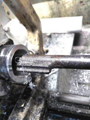
A bit more work produced these parts
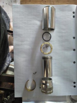
Running down they are the external barrel with the internal thread, an "0" ring seal, a brass retaining ring with 6 x M2 screws, the 4 start internal tube that screws inside, the eyepiece holder with internal brass ring so the clamping screw doesnt mark the eyepiece.
,
They fit together like so, as the threads are greased the "0" ring keeps the grease from coating the tube
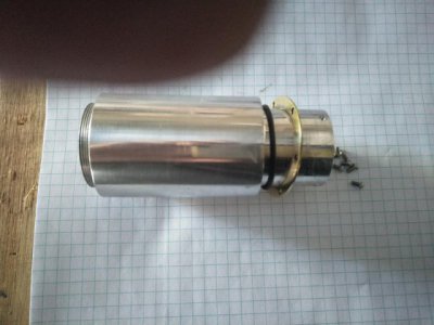
The brass ring sits inside a recess of the eyepiece holder
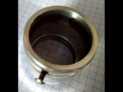
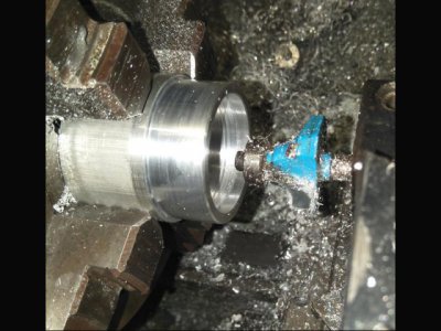
I used the flat edge of a woodworking router bit to cut the recess
This gave me a 4 start thread of M1 pitch where 1 turn gave 4mm of travel.
The hardest part was getting the top slide perfectly aligned with the ways so 1 turn of topslide lead screw went exactly 1mm
I used the hand crank to turn the spindle,
First thread cut to depth then back to the start without disengaging the half nuts.

Advance the top slide 1 full turn (=1mm of travel) and cut the second thread

And continue for the third and fourth cut.

To cut the internal 4 start thread I kept the settings for a 4mm pitch but used an M10x1 tap silver soldered to a bar.
I opted to try this as all 4 starts are cut at the same time so I could use the part above as the test fit to get the correct dia and thread fit.
Again I used the hand crank and didnt disengage the half nuts.

A bit more work produced these parts

Running down they are the external barrel with the internal thread, an "0" ring seal, a brass retaining ring with 6 x M2 screws, the 4 start internal tube that screws inside, the eyepiece holder with internal brass ring so the clamping screw doesnt mark the eyepiece.
,
They fit together like so, as the threads are greased the "0" ring keeps the grease from coating the tube

The brass ring sits inside a recess of the eyepiece holder

I used the flat edge of a woodworking router bit to cut the recess

- Joined
- Aug 22, 2012
- Messages
- 4,271
All assembled fully screwed in, I still have to make the knurled screw for the eyepiece holder.
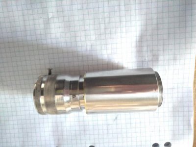
full out travel
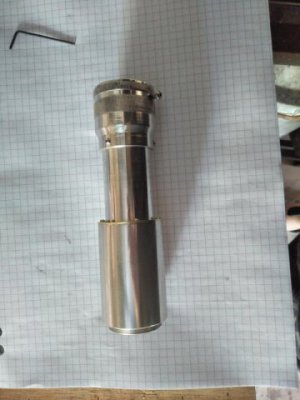
and fully assembled with the 90' diagonal and an eyepiece.
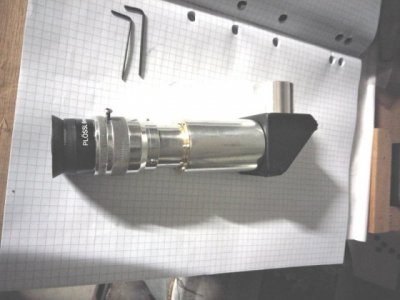
I am very impressed with the smoothness of the action.
Almost finished the second assembly as obviously I need two of these in a bino.

full out travel

and fully assembled with the 90' diagonal and an eyepiece.

I am very impressed with the smoothness of the action.
Almost finished the second assembly as obviously I need two of these in a bino.
