-
Welcome back Guest! Did you know you can mentor other members here at H-M? If not, please check out our Relaunch of Hobby Machinist Mentoring Program!
You are using an out of date browser. It may not display this or other websites correctly.
You should upgrade or use an alternative browser.
You should upgrade or use an alternative browser.
TH54 Atlas lathe rebuild/refurb project (pic heavy)
- Thread starter GoMopar440
- Start date
- Joined
- Oct 19, 2011
- Messages
- 127
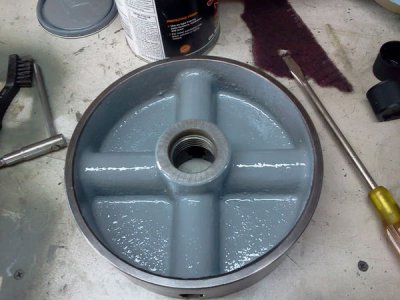
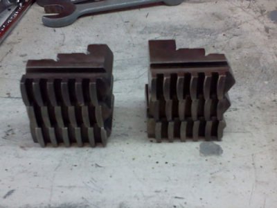
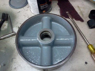
Got a little more done with both of the chucks today. The 4-Jaw got another round of cleaning to get the rest of the deep crud off the back side and rinsed off with carb cleaner before getting a coat of paint (back side only).
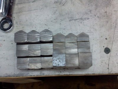
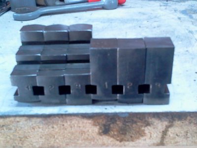
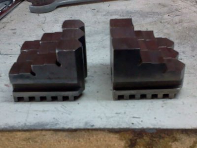
As far as the two sets of jaws for the 3-Jaw, here's a few close up pics to show the details better. Each set is lined up in order, #1, #2, #3 and I tried to get them aligned so you can see the way the teeth are staggered for the scroll. The pointy ends of the jaws are meant to point to the center on both sets. The flatter outside ends (opposite the points) are where the numbers are stamped.
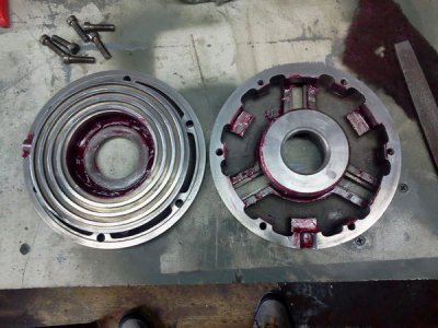
I was able to get the chuck screws out fairly easily by using a cordless hammer drill and a correctly fitting screwdriver bit. The front and back came apart in halves easily enough, but the scroll needed a bit of persuasion (hammer and a punch) to finally come out of the chuck body. The inside was fairly clean, but the scroll plate was a little buggered up on the gear teeth side. A little time with a fine file knocked the rough edges down. The tops of the scroll had a few burrs that were also smoothed over with the file as well. The wire wheel smoothed everything out on both sides of the scroll ring afterwards. I polished the key gear surfaces that ride in the chuck body and cleaned up a few teeth on it as well. The body was then cleaned and degreased with carb cleaner and I used some red waterproof grease on the sliding contact points between the scroll and the chuck body as well as on the gear teeth. The scroll ring went back on easier than it came off, but it was still a close fit.
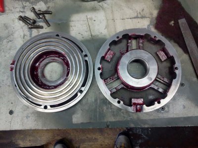
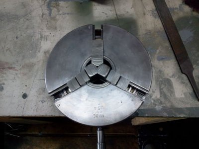
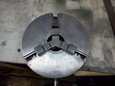
When I put the six screws back in and tightened it down the chuck was smoother, with minimal backlash in the key gear to the scroll ring teeth. The chuck body got a little fine tuning with a file just on the outer edges of the openings for the jaws where there were a couple of small dents that were hindering the jaws. I tried each set of jaws on the chuck and they appear to be timed well. All three jaws meet in the center of the chuck simultaneously on both sets of jaws. Along with my initial observations of the parts, this leads me to believe that both sets of jaws are most likely original to this chuck. I can't get a way to measure for runout until the lathe is back together and I can mount the chuck up to check it.
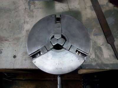
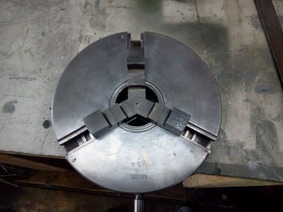
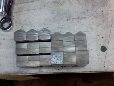
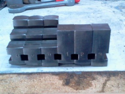
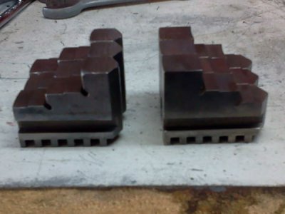
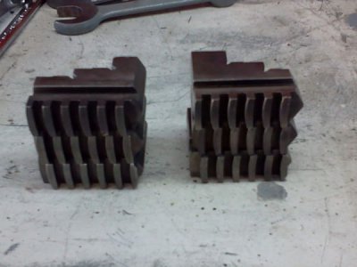

As far as the two sets of jaws for the 3-Jaw, here's a few close up pics to show the details better. Each set is lined up in order, #1, #2, #3 and I tried to get them aligned so you can see the way the teeth are staggered for the scroll. The pointy ends of the jaws are meant to point to the center on both sets. The flatter outside ends (opposite the points) are where the numbers are stamped.


I was able to get the chuck screws out fairly easily by using a cordless hammer drill and a correctly fitting screwdriver bit. The front and back came apart in halves easily enough, but the scroll needed a bit of persuasion (hammer and a punch) to finally come out of the chuck body. The inside was fairly clean, but the scroll plate was a little buggered up on the gear teeth side. A little time with a fine file knocked the rough edges down. The tops of the scroll had a few burrs that were also smoothed over with the file as well. The wire wheel smoothed everything out on both sides of the scroll ring afterwards. I polished the key gear surfaces that ride in the chuck body and cleaned up a few teeth on it as well. The body was then cleaned and degreased with carb cleaner and I used some red waterproof grease on the sliding contact points between the scroll and the chuck body as well as on the gear teeth. The scroll ring went back on easier than it came off, but it was still a close fit.

When I put the six screws back in and tightened it down the chuck was smoother, with minimal backlash in the key gear to the scroll ring teeth. The chuck body got a little fine tuning with a file just on the outer edges of the openings for the jaws where there were a couple of small dents that were hindering the jaws. I tried each set of jaws on the chuck and they appear to be timed well. All three jaws meet in the center of the chuck simultaneously on both sets of jaws. Along with my initial observations of the parts, this leads me to believe that both sets of jaws are most likely original to this chuck. I can't get a way to measure for runout until the lathe is back together and I can mount the chuck up to check it.


I joined this forum because I ran across this thread. I bought one of these lathes, and started taring it down for a full restoration. I'm just enough behind your progress that I can use it as a guide. Thanks for all the information you are offering. The motor on mine was seized up. I took it apart, and after cleaning the rust out of it I can't remember how to put it back together. Staying tuned here, to see if you will have to take yours apart too. Maybe then I can put mine back together the right way. Thanks again
- Joined
- Oct 19, 2011
- Messages
- 127
I'm glad this project is helping others with their own lathes. I'll try to keep it going with notes and pictures of the process as best as I can. If there's anything anyone needs any details on just throw the question out there and I'll answer it as best as I can.
The motor on this lathe was disconnected sometime before I got it. I was told that the old machinist that was using it wanted to use the motor for a project of some kind. However it never got further than him disconnecting it from the lathe before he passed away. I'm not sure if the pulley was broken before or after I got it, but either way it will have to be replaced before I can get this lathe up and running. The power cord is very old and the outer insulation is cracked through to the wires every couple of inches. I'll need to replace the power cord as well as the pulley before using it.
The motor on this lathe was disconnected sometime before I got it. I was told that the old machinist that was using it wanted to use the motor for a project of some kind. However it never got further than him disconnecting it from the lathe before he passed away. I'm not sure if the pulley was broken before or after I got it, but either way it will have to be replaced before I can get this lathe up and running. The power cord is very old and the outer insulation is cracked through to the wires every couple of inches. I'll need to replace the power cord as well as the pulley before using it.
- Joined
- Jun 13, 2013
- Messages
- 23
Your rebuild looks fantastic! Its great inspiration for when I finally get mine and start the restoration. )
)
- Joined
- Jun 13, 2013
- Messages
- 23
I notice that the Atlas chuck only has one tightening lug, this is strange and something I have never seen this before. I presume it works just as well as having the three tightening lugs?
- Joined
- Oct 19, 2011
- Messages
- 127
I didn't get out to the shop today long enough to do anything useful. I did however try plugging in the motor and seeing if it would even spin up. I did get it to spin, but it usually required a little help to get the shaft turning. I'm not sure if the power cord is putting too much resistance on the incoming voltage, the starting capacitor is getting weak or some other problem. Either way the motor will need a tune up, a new power cord and new pulley before it's ready to be put back into service.
- - - Updated - - -
Now that you mention it, I believe it's probably the only one like that (single lug) I've ever come across before. I'd prefer to have three lugs on the chuck for balancing if nothing else. If I had to guess, I'd say it's probably a cost cutting measure designed in to save a few bucks. These aren't very high speed lathes AFAIK so the balance issue wouldn't be as severe as on a high speed machine.
- - - Updated - - -
I notice that the Atlas chuck only has one tightening lug, this is strange and something I have never seen this before. I presume it works just as well as having the three tightening lugs?
Now that you mention it, I believe it's probably the only one like that (single lug) I've ever come across before. I'd prefer to have three lugs on the chuck for balancing if nothing else. If I had to guess, I'd say it's probably a cost cutting measure designed in to save a few bucks. These aren't very high speed lathes AFAIK so the balance issue wouldn't be as severe as on a high speed machine.
- Joined
- Jun 13, 2013
- Messages
- 23
Yes I was thinking about the balance of the lathe, also if the one cog gets worn it might be problematic, the lathe I am getting has the babbit bearings so slow speeds are not an issue.
- - - Updated - - -
That should read balance of the CHUCK, idiot that I am.
- - - Updated - - -
Yes I was thinking about the balance of the lathe, also if the one cog gets worn it might be problematic, the lathe I am getting has the babbit bearings so slow speeds are not an issue.
That should read balance of the CHUCK, idiot that I am.
- Joined
- Oct 19, 2011
- Messages
- 127
I didn't like the feel of the QCGB shifting when I tried moving the levers after I had it off the lathe, so I already knew it was going to get a full teardown. The levers felt sticky but overly loose and kind of jerky when they did move. After looking it over carefully, I started loosening all the locking grub screws and then pulled it all apart. Some of the parts needed to come out first to get out of the way before others could be removed. I'm sure there's a "Best" way to disassemble it, but I just took my time and kept at it till I had it all apart. The last bit to come off was the data plate on the front. To remove that I tapped the little screw rivets (not sure of the exact name for them) from the inside to raise them up a bit. Then I carefully grabbed under the heads with a pair of side cutting pliers, and gently wiggled them out.
The shaft ends all look like they were run without oil for a while at the ends where they ride in the bushings. The bushings didn't have any oil holes in them coming from the oil cups. I'm not sure if that was an oversight when someone may have replaced the bushings in the past, or the wear filled the holes with metal flakes. Either way, it looks like I'll need to get all new shafts and bushings to get this unit back up to 100% condition.
I'm considering reassembling it as is for now until I can find (and afford) the needed replacement parts. I'll definitely have to open up or drill the oil holes in the bushings first though.
My phone was on the charger in the house so I didn't get any pics today.
- Joined
- Dec 25, 2011
- Messages
- 10,552
It is also possible that the bushing are made of sintered bronze. One trade-name is Oilite. These are porous, and wouldn't need an oil hole aligned with the oil supply hole in the QC body casting. I meant to call Clausing last week and ask about that but forgot.
Robert D.
Robert D.
