- Joined
- Feb 8, 2014
- Messages
- 11,176
I got a bit more work done
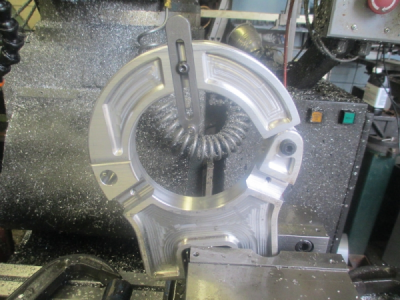
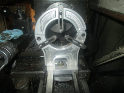
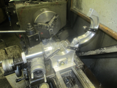
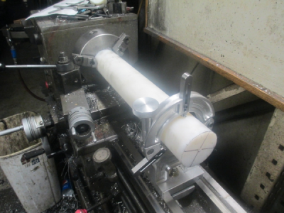
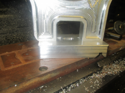
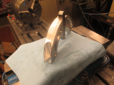
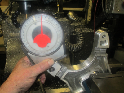
First order of business was to fix my stupid measuring mistake. If you look at the picture, the bottom hangs over the base by 0.193 on each side but worse than that, it is also of center, so 0.013 off of one side and the rest of of the other. The worst part was that it would not fit between the carriage rails.
Double check the measurements before making chips, it will save a lot of work.
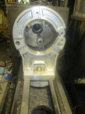
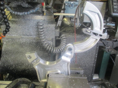
So back in the mill and make the modifications and try to make it look like it was supposed to be that way
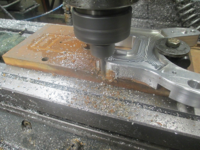
OK it fits now and clears everything, but it looks like crap. This will haunt me every time I use this tool.
OK enough whining.
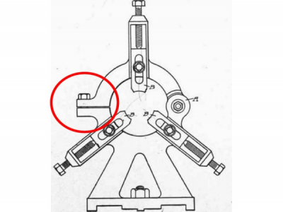
On to the fingers.
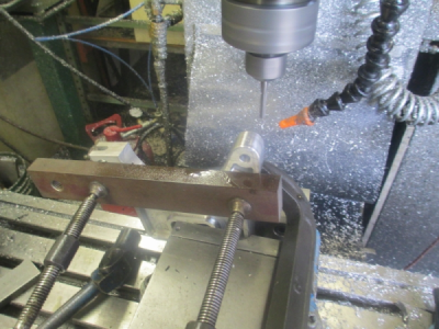
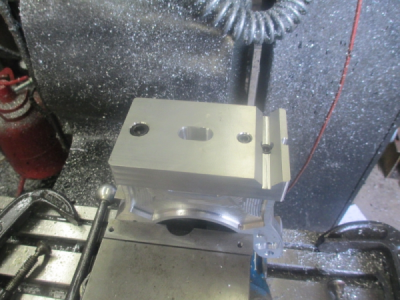
First create a work surface. I was going to bolt down an aluminum plate the the table to mount the work on, but I found this chunk of 6'' aluminum channel in the miscellaneous stock rack, and I needed the vice for the next operations anyway. Had to remove the rear jaw to get it in there. Then of course when you tighten up on a piece of channel it wants to bow up in the center a bit, so a light facing cut to flatten it out.
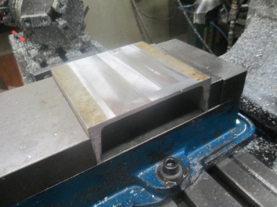
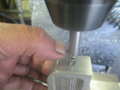
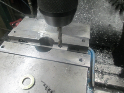
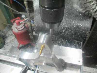
Then drill & tap the mounting holes. These will be used later.
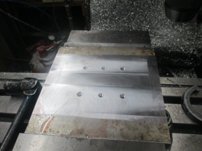
The work piece is 1/2 1018 cold rolled steel. I had to clamp the channel down also because it tried to pull up on me when I was tapping. The pilot holes are also drilled where the pocket start, much easier on the end mill. Even center cutting end mills don't really like plunge cutting. That's why drill bits were invented. For the moment the work is just clamped to the aluminum
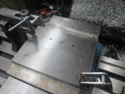
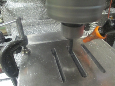
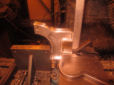
OK, the slots are cut and in the middle of the chamfering operation. I used a 1/4 inch, solid carbide router bit to do the slots. 2400 RPM, 10 IPM, 0.063 DOC. Made the slots 0.260 wide for bolt clearance.
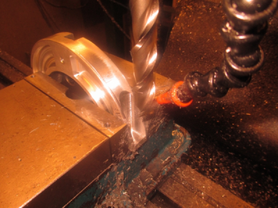
Here is the work screwed down. And starting the outside profile operation. Remember what I said earlier about end mills not liking plunge cutting? Well I should have drilled pilot holes because on the next pass after this picture the router bit shattered. It was plunging too fast. I guess I got pretty good life out of that one anyway, it had done all of the work on this entire project up to this point and a few others. Router bits are not quite as robust as end mills, the web is a bit thinner. But they cut great, are razor sharp, and available on a Saturday afternoon at your local big box store.
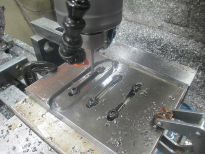
The only sharp 1/4 inch end mill that I could fine was a HF 4 flute. It did the job but it won't run as fast as the carbide so I had to slow the feed down also. So about 90 minutes to cut these 3 pieces out, including the tool change.
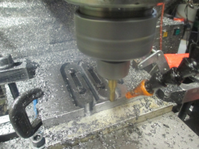
and the near finished parts with the bearing mount holes drilled, tapped, and reamed to depth.
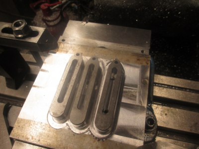
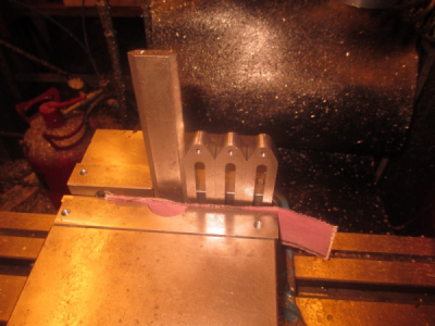
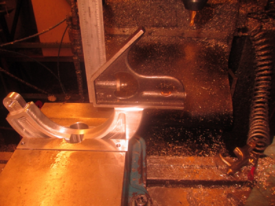
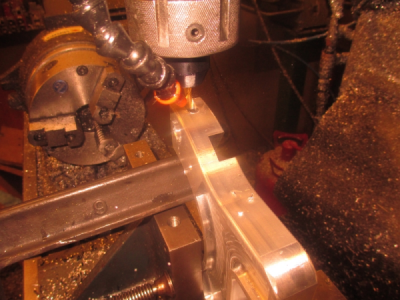
Now for the bearing clearance. Just lined them up in the vice, squared them up, and away we go Note the emory cloth between the movable jaw and the parts, grit side to the parts, that insures that nothing is going to move.
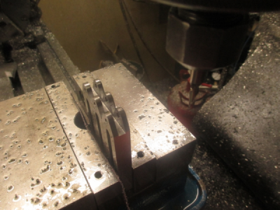
And the slots complete. 3/16 cobalt, 2 flute. 10IPM 0.035 DOC, 1800 RPM. The slots are 0.520 deep to clear the 0.500 bearing. I would have used 0.750 bearings, but I had 0.500 in stock.
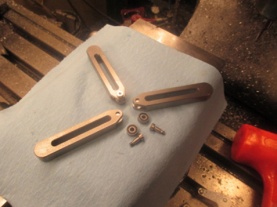
And the completed fingers
This will handle a full 4.5 diameter part in the lathe and go as small as about 1/8 inch.
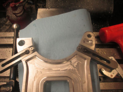
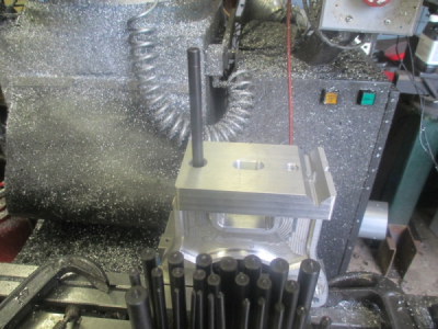
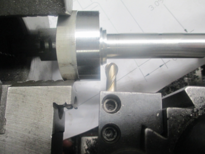
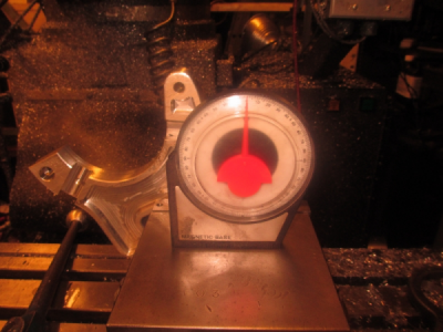
A little teaser for the next operations Stay tuned!............
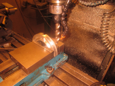
First order of business was to fix my stupid measuring mistake. If you look at the picture, the bottom hangs over the base by 0.193 on each side but worse than that, it is also of center, so 0.013 off of one side and the rest of of the other. The worst part was that it would not fit between the carriage rails.
Double check the measurements before making chips, it will save a lot of work.


So back in the mill and make the modifications and try to make it look like it was supposed to be that way

OK it fits now and clears everything, but it looks like crap.

OK enough whining.

On to the fingers.
First create a work surface. I was going to bolt down an aluminum plate the the table to mount the work on, but I found this chunk of 6'' aluminum channel in the miscellaneous stock rack, and I needed the vice for the next operations anyway. Had to remove the rear jaw to get it in there. Then of course when you tighten up on a piece of channel it wants to bow up in the center a bit, so a light facing cut to flatten it out.

Then drill & tap the mounting holes. These will be used later.

The work piece is 1/2 1018 cold rolled steel. I had to clamp the channel down also because it tried to pull up on me when I was tapping. The pilot holes are also drilled where the pocket start, much easier on the end mill. Even center cutting end mills don't really like plunge cutting. That's why drill bits were invented.

OK, the slots are cut and in the middle of the chamfering operation. I used a 1/4 inch, solid carbide router bit to do the slots. 2400 RPM, 10 IPM, 0.063 DOC. Made the slots 0.260 wide for bolt clearance.

Here is the work screwed down. And starting the outside profile operation. Remember what I said earlier about end mills not liking plunge cutting? Well I should have drilled pilot holes because on the next pass after this picture the router bit shattered. It was plunging too fast.

The only sharp 1/4 inch end mill that I could fine was a HF 4 flute. It did the job but it won't run as fast as the carbide so I had to slow the feed down also. So about 90 minutes to cut these 3 pieces out, including the tool change.

and the near finished parts with the bearing mount holes drilled, tapped, and reamed to depth.

Now for the bearing clearance. Just lined them up in the vice, squared them up, and away we go

And the slots complete. 3/16 cobalt, 2 flute. 10IPM 0.035 DOC, 1800 RPM. The slots are 0.520 deep to clear the 0.500 bearing. I would have used 0.750 bearings, but I had 0.500 in stock.

And the completed fingers

This will handle a full 4.5 diameter part in the lathe and go as small as about 1/8 inch.

A little teaser for the next operations



 Steve Shannon
