- Joined
- Feb 8, 2014
- Messages
- 11,176
My lathe did not come with a steady rest and for the first time in over 20 years I actually need one for a project. I have to drill a 1 inch hole about 20 inches deep through a UHMW rod about 3.5 inches dia. Way too much stick out to do it unsupported. When I get to that project I'll post showing how I did it.
I looked on line for a steady rest that might fit my lathe, but what I found were all much too small to handle anything close to 3.5 inches. I can put 6 inch diameter over my cross slide, so you would think that a little bigger hole would be available in a steady rest.
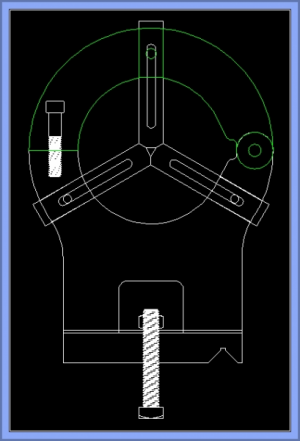
OK, so sit down and design a steady rest that will do what I want. This one will handle a max of 4.5 inches. The design has changed slightly from this drawing. There will be bearings added to the fingers. But I will also make a set of brass fingers with no bearings. The clamp bolt design has also changed to a swing away clamp.
I spent most of the day digging the top part out of a chunk of 4x7.5x1 6061.
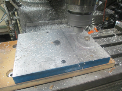
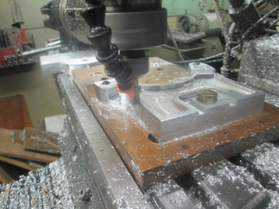
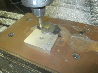
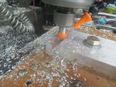
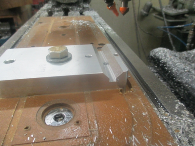
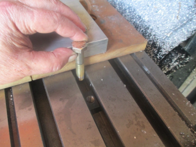
I bolted the part down to a MDF spoil board with one 1/2 inch bolt to a T-nut under. Then drilled and tapped for 1/4-20 right into the MDF just to prevent any possible rotation when machining. I started by pocketing the lightning relief, not really to make it lighter, but just to make it look more professional.
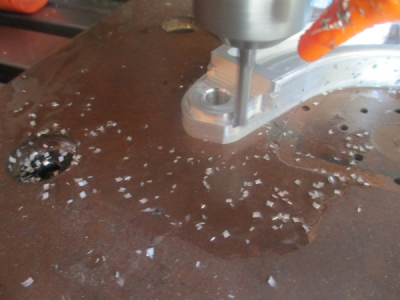
1/4 inch, 2 flute, solid carbide router bit. 2400 rpm, 10 IPM, 50/50 mix of kerosene and WD-40 for cutting fluid. I limited the depth of cut to 0.063 because the setup was not the most robust. I would have rather had more bolts in there but no place to put them.
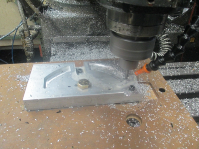
Putting the radius in the bottom of the pockets, just to make it look nice.
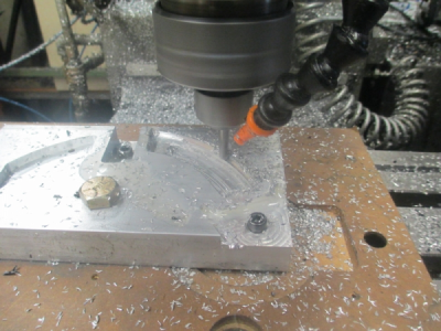
Profiling the outside surfaces. This is where it gets a little dicey, I wasn't sure how things were going to react when the piece that is bolted down with the 1/2 inch bolt gets cut loose from the actual part. There is not much holding things down. I went outside until this part of operation completed to get a wall between me and the machine, I didn't want to get hit with flying carbide. As it turned out, everything was well behaved, and went exactly as planned.
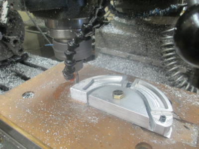
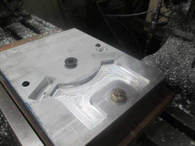
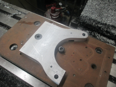
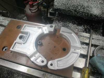
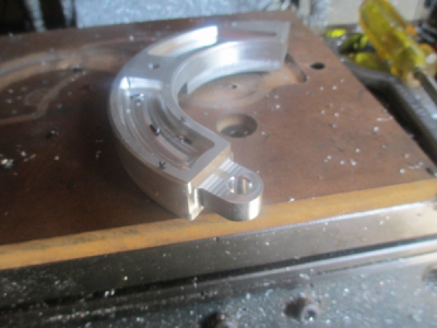
And the back side of the top is complete. That little flat on the hinge radius was not designed in, I really needed 4.125 wide material but only had 4 inch. No problem, it will work fine, and that part is hidden anyway.
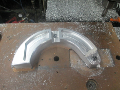
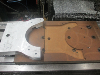
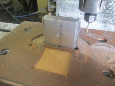
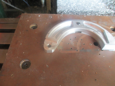
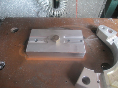
Now for the other side. First I machined a 0.250 deep pocket into the MDF with the same profile as the part. This allowed a press (OK, hammer ) fit that captured the part and holds it securely. As you can see, this spoil board has been used for a few other projects. Just about past it's useful life.
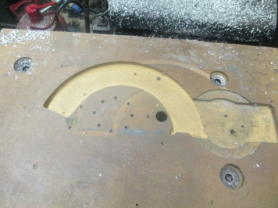
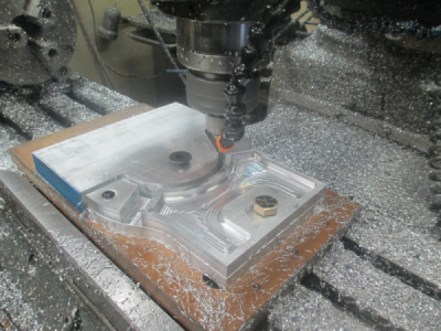
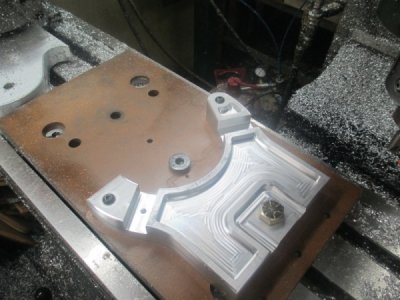
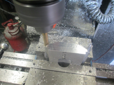
Pocketing the front side. The part is held down by one 1/4-20 cap screw threaded into the MDF, it really can't go anywhere, and I probably didn't need the cap screw, but a little extra insurance doesn't hurt.
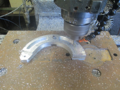
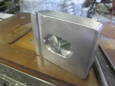
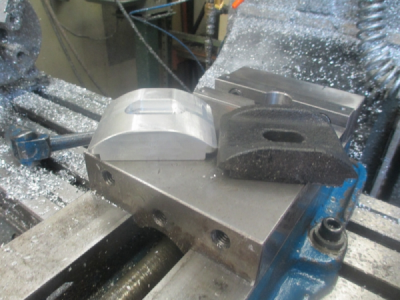
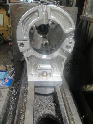
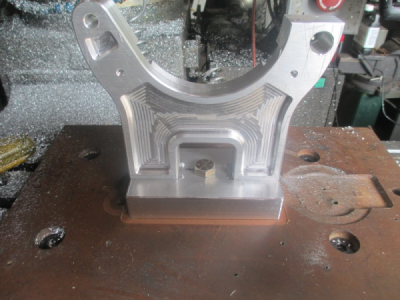
And the (almost) finished part. I have to do the clearance and slot for the clamp bolt, but that will be after I get the rest of the parts done and put the vice back on.
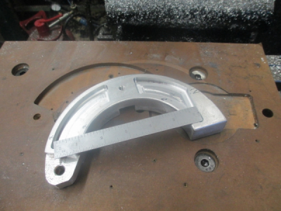
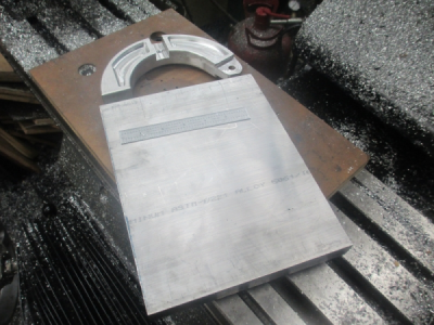
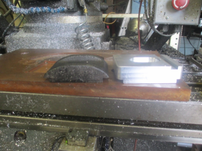
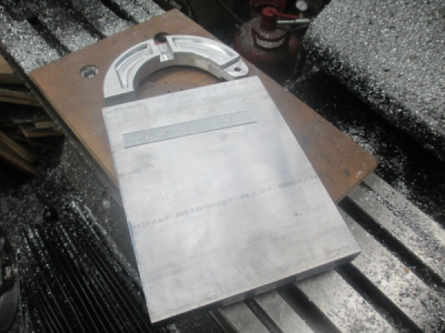
Somewhere in that 8x10x1 chunk of aluminum is the bottom, I'll dig around in there tomorrow and see if I can find it.
I looked on line for a steady rest that might fit my lathe, but what I found were all much too small to handle anything close to 3.5 inches. I can put 6 inch diameter over my cross slide, so you would think that a little bigger hole would be available in a steady rest.
OK, so sit down and design a steady rest that will do what I want. This one will handle a max of 4.5 inches. The design has changed slightly from this drawing. There will be bearings added to the fingers. But I will also make a set of brass fingers with no bearings. The clamp bolt design has also changed to a swing away clamp.

I spent most of the day digging the top part out of a chunk of 4x7.5x1 6061.
I bolted the part down to a MDF spoil board with one 1/2 inch bolt to a T-nut under. Then drilled and tapped for 1/4-20 right into the MDF just to prevent any possible rotation when machining. I started by pocketing the lightning relief, not really to make it lighter, but just to make it look more professional.
1/4 inch, 2 flute, solid carbide router bit. 2400 rpm, 10 IPM, 50/50 mix of kerosene and WD-40 for cutting fluid. I limited the depth of cut to 0.063 because the setup was not the most robust. I would have rather had more bolts in there but no place to put them.

Putting the radius in the bottom of the pockets, just to make it look nice.

Profiling the outside surfaces. This is where it gets a little dicey, I wasn't sure how things were going to react when the piece that is bolted down with the 1/2 inch bolt gets cut loose from the actual part. There is not much holding things down. I went outside until this part of operation completed to get a wall between me and the machine, I didn't want to get hit with flying carbide.
 As it turned out, everything was well behaved, and went exactly as planned.
And the back side of the top is complete. That little flat on the hinge radius was not designed in, I really needed 4.125 wide material but only had 4 inch. No problem, it will work fine, and that part is hidden anyway.

Now for the other side. First I machined a 0.250 deep pocket into the MDF with the same profile as the part. This allowed a press (OK, hammer

Pocketing the front side. The part is held down by one 1/4-20 cap screw threaded into the MDF, it really can't go anywhere, and I probably didn't need the cap screw, but a little extra insurance doesn't hurt.

And the (almost) finished part. I have to do the clearance and slot for the clamp bolt, but that will be after I get the rest of the parts done and put the vice back on.

Somewhere in that 8x10x1 chunk of aluminum is the bottom, I'll dig around in there tomorrow and see if I can find it.


